
5G UEs pose a major challenge for device designers. The inherently lower power added efficiency at mmWave, compared to traditional cellular bands, leads to devices operating at higher temperatures while simultaneously reducing battery life. The simplified architecture for DPD with HBF is particularly important in handset UEs for this reason, as early 5G handsets have seen thermal issues with multiple mmWave arrays in a confined physical envelope. Mass-market UEs also have even more stringent cost requirements than gNBs, with a constant “race-to-the-bottom” in price pushing designers to embrace novel technologies if they have a corresponding cost decrease.
As a contrast to 5G gNBs and UEs, 5G repeaters are less defined in standards. Generally, repeaters reproduce an incoming signal with minimal processing, typically limited to L1 (physical layer) or L0 (RF layer) only. Regardless of whether a repeater processes a signal at L0 or L1, beam forming is needed to support mobile network operator (MNO) requirements. The cost, complexity and power draw are expected to be less than a full gNB, allowing repeaters to serve as network extension nodes without the effort of deploying a complete gNB. Cost is a major driver for repeater deployment by MNOs: the lower the cost, the more easily repeaters can be deployed to cover gaps in the network. HBF is thus a natural fit for the beam forming subsystem of a 5G mmWave repeater.
When compared to a full gNB solution, repeaters do not need full-stack processing to operate. The lower the layer of processing, the lower cost of the signal processing chain, as FPGAs and ASICs are not required. A L0 repeater consists primarily of a system controller, power supply and management unit, RF chain(s) and beamformer(s). These modules are required in a L1 repeater with the addition of frequency conversion (to IF or I/Q), ADC/DAC chains and baseband processing. L0 repeaters provide the lowest cost architecture, while L1 repeaters can provide additional signal conditioning in the presence of interference.
Repeaters extend a signal to locations unreachable by the original source. As an example, the free space path loss at 28 GHz is approximately 71 dB 10 ft. from the source. A repeater which extends coverage to an additional 10 ft. (say from a window, inside a home) should have at least 71 dB of gain to compensate. With typical window or wall penetration loss adding at least 5 dB, this example repeater needs 50 dB of electronic gain with an additional 26 dB of gain contributed by the Tx and Rx antennas.
With a restriction to L0-only processing, the repeater must be able to remain unconditionally stable across all deployment environments: this presents the fundamental design issue for repeaters given the large electronic gain required within a single enclosure. Careful RF design is needed to prevent oscillation under any conditions, as stability is affected by temperature, scattering environment and even window material. Pivotal’s L0 repeater using HBF has been proven in real-world deployments to effectively extend the coverage of mmWave in both indoor and outdoor settings. The use of low-cost mmWave repeaters is a crucial piece in the 5G deployment puzzle to avoid over-deployment of gNBs, which leads to a node density and cost that is unacceptable for MNOs.
5G mmWAVE HBF REPEATERS IN FIELD TRIALS
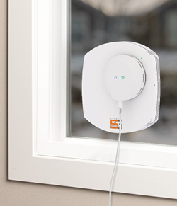
Figure 6 Pivotal Echo 5G™.
Penetration through building material presents a challenge for mmWave deployments. It is not uncommon to encounter over 40 dB of loss when transitioning from outdoor to indoors. Since the channel is reciprocal, the same degradation occurs in the uplink direction, from UE to gNB. To overcome mmWave propagation and outdoor to indoor penetration loss, Pivotal Commware created two mmWave beam forming repeater products: the Echo 5G (see Figure 6), a self-installable, tablet-sized, on-the-window, beam forming repeater for facilitating outdoor to indoor propagation, and the Pivot 5G, a professionally installed network element/repeater for supplementing and, in some cases, replacing gNB in commercial network deployments. This setup has been tested in numerous environments with a U.S.-based carrier and commercial gNBs and has completed interoperability testing with network equipment from three gNB vendors.
Apartment Buildings
Pivotal conducted one trial in a suburban apartment building shown in Figure 7. The gNB was located 700 ft. away and a commercial UE was inside the home. The Echo 5G was placed on the patio window (in yellow) with line-of-sight (LOS) to the gNB at 45 degrees from window broadside (parallel arrows). The unobstructed gNB-to-UE link supported peak throughput of 1.5 Gbps. The UE was then moved around the interior and tests run in various locations within the apartment.
The two pictures in Figure 7 depict “before and after” the unit was utilized. Figure 7 summarizes throughput results. The results printed in green are all LOS locations from the unit. The results in amber are non-LOS locations from Echo that Echo still served very well.
Without this product, full rate was only observed by placing the UE at the balcony door, as most of the interior was mmWave shadowed by the building wall (in red). Only the kitchen area indoors was not in the mmWave shadow, as it had LOS connectivity to gNB through the window. For other test locations, a mostly full rate experience was observed and locations that previously had no connectivity showed substantial throughput. Signal level measurements showed 20 to 30 dB improvement.
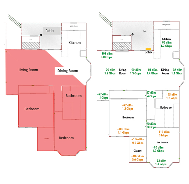
Figure 7 Suburban apartment trial results, before and after Echo 5G deployment.
The number of gNBs needed to cover an area is the dominant factor in calculations of CAPEX and OPEX associated with a network deployment. This type of unit reduces the number of initially needed base stations dramatically, with 1 km distant LOS links becoming possible even with outdoor to indoor penetration challenges.
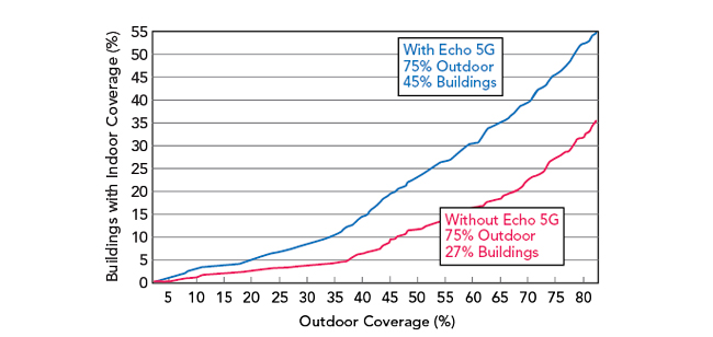
Figure 8 Outdoor vs. indoor coverage, urban, without Echo (red) and with Echo (blue).
Modeling suggests the served addressable market (SAM) can be doubled, even quadrupled, if this product is utilized to bring the mmWave signals indoors without adding additional gNBs. Figures 8 and 9 show projections for urban and suburban environments, respectively. In both figures, the baseline is achieved outdoor coverage (x-axis). The benefit Echo 5G brings is the additional indoor coverage (y-axis) depicted with the blue line in each of the plots.
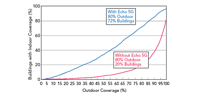
Figure 9 Outdoor vs. indoor coverage, suburban, without Echo (red) and with Echo (blue).
Repeater Applications
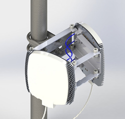
Figure 10 Pivot 5G prototype.
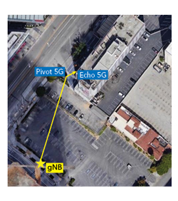
Figure 11 Live demo setup for MWC Los Angeles 2019.
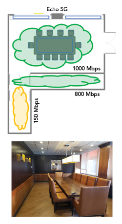
Figure 12 The layout of the indoor space and photo of the boardroom.
Pivot 5G is an outdoor network repeater shown in Figure 10. As a base station proxy, the unit redirects mmWave signals from the gNB around obstacles and extends the range of 5G base stations.
A bring-your-own-device demonstration was set up for MWC Los Angeles 2019. This demonstrated Echo 5G and Pivot 5G in a real-world environment, with commercial gNB and 5G UEs. The demo location was a meeting boardroom near the MWC venue, and the room lacked LOS to the gNB. Echo 5G was deployed on the window facing South Figueroa Street. From this position, the Echo 5G was located 300 ft. away from the gNB but lacked LOS to the gNB. Pivot 5G was deployed in the hotel parking lot to redirect coverage to Echo 5G. The topology is depicted in Figure 11.
Testing used a standard Samsung S10 5G phone. Each of the demos was benchmarked from inside the boardroom showing that 5G throughout is impossible without the units. In each test, the phone either could not connect to 5G or it connected with low throughput (< 100 Mbps). With Echo 5G and Pivot 5G on, throughput of 1000 Mbps on the 5G network, with the phone positioned 15 to 20 ft. in LOS of the Echo 5G, was consistently observed.
Moving into a hallway behind the boardroom, the phone did not initially connect to 5G. With the Echo 5G and Pivot 5G turned on, throughput of 800 Mbps was shown even with the phone positioned 20 to 30 ft. away and not in LOS of the Echo 5G.
Finally, 150 Mbps was achieved in a second hallway - two boundaries and over 30 ft. away from the window - by the Echo 5G and Pivot 5G. Without them, there was no 5G reception. The layout and the results are depicted in Figure 12.
SUMMARY
This article demonstrated the importance of beam forming in 5G mmWave networks and described three beam forming technologies: phased arrays, MU-MIMO and HBF. It claimed that HBF is particularly well-suited to 5G mmWave system designs and explained why, from a systems perspective, the use of low-cost mmWave repeaters is a crucial piece in the 5G deployment puzzle to avoid over-deployment of gNBs. Finally, the article elaborated on field trials and early success stories associated with 5G mmWave repeaters that use HBF.n