
Figure 5 Integrated single layer six port PCB.
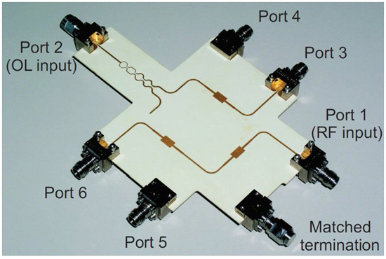
Figure 6 Multilayer microstrip slot transition with four stage Wilkinson PD.24
The Following are examples six port single layer substrate board designs:
Single section branch line coupler (BLC):
Ibrahim et al.12 assess a six port network from 5 to 8 GHz for DOA detection. It uses a single section BLC and Wilkinson PD. The bandwidth of the BLC is enhanced with λ/4 transformers at all ports. The measured S parameters of fabricated components is used to form a six port ADS simulation model; the six port circuit, as a whole, is not built. The results are tabulated in Table I. The phase imbalance is 90 +5 degrees. Amplitude imbalance among the transmission coefficients is 2 dB, which is slightly higher than desired.
Mohsin et al.13 report on a 6 to 9 GHz six port network using single section BLCs with inside folded stubs, increasing the bandwidth from 10 to 50 percent. A single stage Wilkinson PD is used.
Koelpin et al.6 describe an integrated six port receiver at 24 GHz (see Figure 5) with a six port circuit in the middle comprising single stage BLCs, bandpass filters, power detectors and baseband amplification circuitry.
Double section BLC design:
Askari and Kamarei10 use a double section coupler design in a six port circuit for 5 G applications. The use of a double section coupler provides a broad bandwidth between 21 and 30 GHz. In multi-section branch line couplers, however, impedances of the vertical branch lines increase considerably. This decreases the widths of corresponding microstrip lines to micrometers, making them difficult to fabricate.
Abdullah et al.’s14 design of a complex ratio measurement system uses a six port network between 2.5 and 5.2 GHz. Double section BLCs are used with slots in the ground plane to increase bandwidth. Additional stubs on all three ports of the Wilkinson PD also serve to enhance bandwidth.
Elliptical patch offset port coupler design:
A six port based phase correlator is used for DOA detection using elliptical patch offset port couplers.15, 16 The six port network is simulated and experimentally tested from 3 to 8 GHz. Wide bandwidth is achieved using an elliptical patch quadrature coupler design. Quadrature phase at the output port is achieved by varying the major axis and the angle of the output ports with respect to the major axis. The minor axis and step impedance width and length are optimized to achieve the best isolation and return loss. A double stage Wilkinson PD enhances the bandwidth. Although wide bandwidth is achieved, reported phase performance is 30 degrees, which is inadequate for precise phase detection applications.
In the following examples, multilayer design is used, where two or more substrate boards are joined to achieve compact size and wider bandwidth:
Elliptical microstrip slot directional coupler (MSDC):
Ultra-wideband (UWB) six port networks from 3.1 to 10.6 GHz demonstrated by Bialkowski et al.17 use multilayer microstrip slot transitions.18-21 Two 0.5 mm substrates are joined such that ground is formed at the center with signal layers at top and bottom. The multilayer coupler has input and output ports on both sides of the combined substrates. The physical dimensions of the elliptical microstrip patches and ground slots depend upon the even and odd mode impedances of the coupled structure which in turn depend upon the desired coupling values. A similar slot transition coupler is designed by Abbosh and Bialkowski22 using multi-section elliptical microstrip patches.
Two different multilayer UWB 180 degree PDs are designed and fabricated. One uses a stripline input port and two microstrip output ports on different layers. The other23 uses a microstrip slotline transition technique for the PD. The advantage of the second design is that its microstrip input port can easily be integrated with other microstrip components. A multioctave bandwidth and a compact size of 43x43 mm is achieved using the multilayer microstrip slot transition.
Wei et al.18 use a similar elliptical slot coupled coupler, however a multi-section Wilkinson replaces the multilayer PD. The two components are integrated with an impedance controlled via having a fractional bandwidth of 190 percent. The complete network operates from 0.5 to 4 GHz.
Stripline multi-section cascaded design:
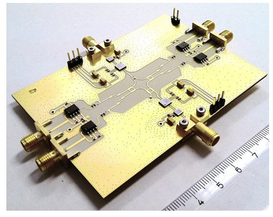
Li et al.25 demonstrate a wideband six port network operating from 2 to 8 GHz. The use of broadside coupled multi-section stripline couplers26 yields a very wide bandwidth. A four section Wilkinson power divider achieves a wider bandwidth in suspended stripline while providing low dissipation, good temperature performance and batch consistency. The 3 dB quadrature couplers are realized using two 8.34 dB couplers in series using coupled stripline technology. A via hole is provided to connect one of the output ports of divider with a bottom broadside coupled stripline layer. The multi-section coupler design includes a 7-section quarter wave transformer, which also improves bandwidth. Individual components transmission and reflection coefficients are measured,26 and measurements of the integrated six port network are in Table I. This design provides a multioctave bandwidth at the cost of larger size. The network is shown in the Figure 7.
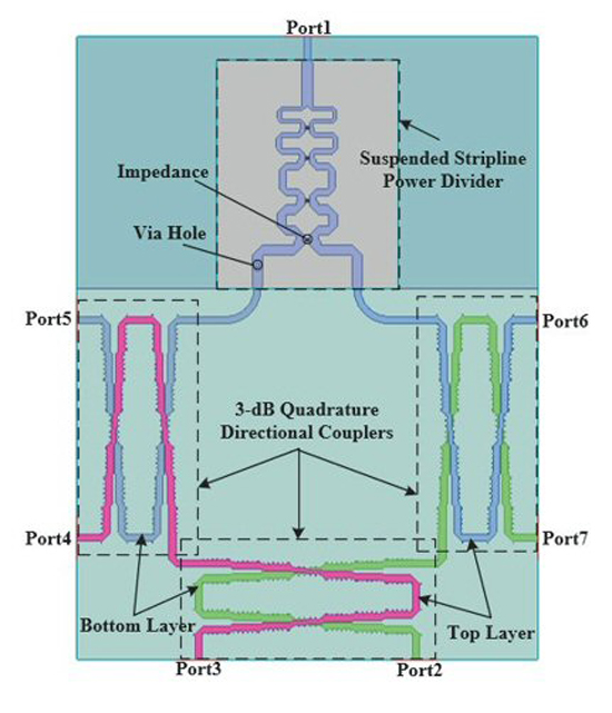
Figure 7 Multilayer six port network based on series connected multi-section stripline couplers and dividers in suspended stripline.25
Rectangular meandering:
Winter et al.27 propose a multilayer six port design based upon a rectangular meandering (zig-zag pattern) where the size can be reduced by 79 percent, making MMIC implementation possible. Like Abbosh and Bialkowski,22 the signal layers are on the top and bottom with ground in the center. Twelve vias are incorporated at the input and output ports to connect the top and bottom signal layers. The strength of this design in comparison with others is its compactness with final dimensions of (0.025 x 0.19) λ at 2 GHz.
Topology 2 (power dividers and 90 degree phase shifters)
In this topology, the six port circuit is realized using power dividers and 90 degree phase shifters; however, the signal must travel through three components, which increases theoretical insertion loss to 9 dB.
The single layer substrate design in the following not only provides ease of fabrication but also eliminates the alignment related errors inherent in multilayer designs.
90 degree phase shift by vertical microstrip to co-planer waveguide (CPW) transition:
Ibrahim et al.28 use only in-phase and quadrature phase Wilkinson power dividers versus the conventional topology. Wide bandwidth from 3.5 to 9 GHz is achieved using dual section vertical interconnect microstrip to coplanar waveguide (CPW) transitions as 90 degree phase shifters.29 This single layer approach eliminates a matched termination, which is present in other designs. The top and bottom layers can be seen distinctly in Figure 8. The authors use six in-phase and four quadrature phase power dividers. Each signal passes through two dividers and one combiner.
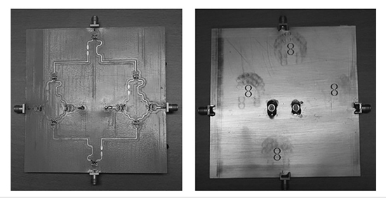
Figure 8 The top (a) and bottom (b) layers of a six port network based on I/Q Wilkinson power dividers.28
A broad band 90 degree phase shift is achieved with a dual vertical interconnect microwave to CPW transition.29 This uses two pairs of broadside coupled elliptical sections on the top and bottom layers. The bottom layer sections are connected by a small strip of microstrip line. The differential phase shift can be controlled by tuning the minor axis of the broadside coupled elliptical sections. As previously mentioned, the downside of this design is greater insertion loss which is reported to be 11 +2 dB.
Ground slotted technique:
Yusof et al.30 use the ground slotted technique in a single board to achieve ultra-wide bandwidth from 3.1 to 10.6 GHz. The six port network is designed using four in-phase two section power dividers and two 90 degree power dividers. A 90 degree phase shift is achieved using two parallel coupled microstrip lines on the top layer and a corresponding zig-zag pattern slot in the ground layer. Double section in-phase power dividers with rectangular slots in the ground plane further enhance the bandwidth (see Figure 9). This achieves the same ultra-wide bandwidth as the slot coupled approach, however it has a greater insertion loss of 10 +2 dB, limiting its use in high sensitivity applications.
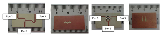
Figure 9 Ground slotted techniques shown with top and bottom layers: 90 degree power dividers (a), (b) and in-phase power dividers (c), (d).30
Topology 3 (Four QHCs and 90° phase shifter)
In this topology, the six port circuit is realized using four QHCs and a 90 degree phase shifter.
Single layer design
Ring hybrid coupler design:
A new beam direction finding circuit based on six port technology employs four ring QHCs along with an integrated delay line quadrature phase shifter to realize a six port network fabricated using miniaturized hybrid microwave integrated circuit (MHMIC) technology.31-33 The complete setup provides multiband operation at 2.45, 5.8 and 9.4 GHz. The network is simulated in ADS and fabricated. The results include I,Q signal graphs versus phase difference between two incident RF signals and the angle of arrival. The authors describe how a quadrature signal increases from zero to maximum with the increase in angle of incidence. Hence, an alternate trivial method of finding DOA has been suggested by just monitoring the quadrature signal.
Multilayer design
Microstrip slot coupled phase shifter:
Moscoso et al.34 use four multilayer MSDCs along with a slot coupled double section quadrature phase shifter, which is the prominent feature of this design. The authors claim that the use of four identical MSDCs help to cancel most of the structure’s intrinsic phase errors. This claim is supported by a measured phase imbalance of just 2.5 degrees, which is due solely to the quadrature phase shifter.
Operational enhancements in six port design
This article focuses primarily on direction finding, so the operational enhancements discussed below identify improvements in six port network design for DF systems.
Dual angle detection:
Hussain and Sharawi35 describe a dual channel six port network for angle of arrival detection in both azimuth and elevation employing a planar antenna array with four patch antennas in a square configuration. It has a multilayer PCB design in which the top and bottom layers are used for channels 1 and 2 of a six port network. It is designed to operate from 1.68 to 2.25 gHz with a bandwidth of 570 MHz. The authors selected a Topology 3 six port design using hybrid ring quadrature couplers and a 90 degree delay line phase shifter. A compact size of (0.43 x 0.43 x 0.01)λ at 2 GHz achieves a dual angle capability utilizing a multilayer architecture.