
The six port network has emerged as a successful receiver architecture with application in metrology, communications, remote sensing, displacement/misalignmentdetection and direction finding due to its precise phase measurement resolution and accuracy. Over the years various design techniques have been used depending upon the application and desired performance specifications. In this article, a comprehensive taxonomy of six port architectures and design techniques is presented under various categories such as topology, number of layers and prominent design features. Furthermore, a comprehensive comparative analysis among different six port design techniques is carried out based on key performance characteristics including operating bandwidth, design complexity, insertion loss, return loss, transmission coefficients, phase performance and physical characteristics. Advantages gained by multilayer and multi-section approaches in terms of bandwidth and compactness are discussed. Basic operation is presented making use of simple analytical expressions suitable for a direction finding (DF) or angle of arrival (AOA) detection system. Various operational enhancements with respect to direction finding are also included, such as extended field of view (FOV) and dual angle detection (azimuth and elevation). Open problems and future research directions are suggested based on the survey.
A direction finding system measures the AOA of an intercepted electromagnetic (EM) signal with respect to the host platform or some reference axis. Locating a signal source is of critical importance both from a civilian and military perspective. There are numerous commercial DF applications such as search and rescue, navigation, automotive radars, misalignment detection, astronomy and telecommunications.
Military applications of direction finding or AOA estimation may be more obvious. In electronic warfare, a direction finding receiver is integrated with an electronic intelligence (ELINT) receiver providing AOA information which helps in initial sorting of an intercepted signal. Similarly, a moving intercept platform with a DF system can triangulate hostile radars based on several converging lines of bearing (LOBs), which results in the formulation of an electronic order of battle (EOB). Moreover, a DF system can provide early warning of an impending attack and help the host platform take appropriate evasive maneuvers. In a potent electronic attack system, AOA information of a hostile emitter can also be used to jam it effectively.
AOA estimation or direction finding has been accomplished using different architectures and techniques since the advent of radio waves. The basic techniques can be divided into Amplitude Comparison, Phase Comparison (Interferometry), Time Difference of Arrival and Frequency Difference of Arrival. Single or multiple channel DF receivers can be used depending upon the complexity of the system. It is well established that phase interferometry provides the best angular resolution and accuracy.1, 2
Phase interferometry can be implemented in both the digital signal processing (DSP) and microwave domains as shown in Figure 1. DSP based solutions require large antenna arrays consisting of multiple antenna elements, coherent receivers to preserve phase and amplitude information, multiple analog-to-digital converters (ADCs) and DSPs adding to overall cost and complexity. Some AOA estimation algorithms used extensively are Multiple Signal Classification (MUSIC), Estimation of Signal Parameters using Rotational Invariance Technique (ESPRIT), Maximum Likelihood Estimation (MLE) and Correlative Phase Interferometry.1, 2
Alternatively, most DF processing can also be carried out in the microwave domain. In multiple microwave-based DF solutions, a four port phase comparator is used to detect the phase difference between incident signals received at its two input ports from which AOA is determined. The phase difference is computed from the I/Q signals at its two output ports. This technique provides reasonable angular accuracy; however, the use of mixers in its architecture adds inaccuracy in phase detection.3 Moreover, at high frequencies the design of active mixers and direct conversion components becomes difficult. Phase noise and DC offset are also generated at a mixer output port due to local oscillator (LO) leakage and amplitude imbalance between RF and LO ports. Due to these inherent limitations, an alternate receiver architecture based on a six port phase comparator has been adopted in DF applications for the last decade. This phase detector design eliminates mixer inaccuracies by using only passive elements.
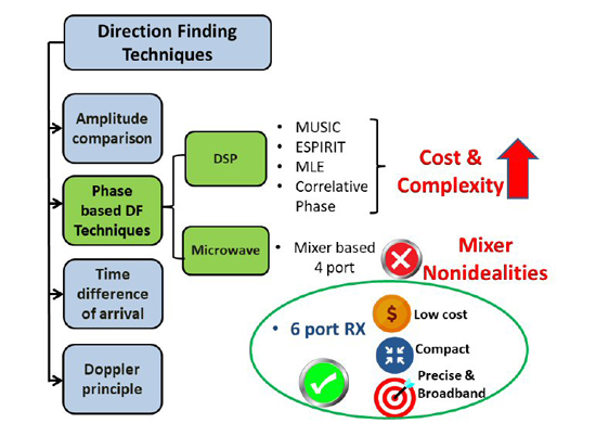
Figure 1 Six port interferometry compared with DSP based algorithms.
SIX PORT NETWORK BASICS
The advent of six port technology dates back to 1972 when Engen4 described its applications in power measuring devices; however, as planar microstrip design and fabrication technology was not mature enough at that time, it did not gain much popularity. It is only in the last decade that the engineering community has started to realize six port applications in numerous fields.
A six port network can also be called an RF interferometer.5 The overall architecture of a six port network, along with input/output signals at each component, is shown in Figure 2. It is an alternative homodyne receiver architecture that provides vector measurement of the two complex input signals by taking scalar measurements at its four output ports. It achieves this through the superposition of the two input signals, producing relative phase shifts of 0, 90, 180 and 270 degrees between the incident signals at its four output ports.5-8 These superpositions and relative phase shifts are carried out using a network of 0/180 degree power dividers, quadrature hybrid couplers and 90 degree phase shifters. Depending upon the inherent phase shift between the incident signals, they interfere constructively or destructively at the four output ports. Diode power detectors are then used at the output ports to convert high frequency signals to baseband voltages. The diodes behave as ideal square law detectors, i.e. the voltage at the output of the detector is proportional to the square of the magnitude of the input waves.
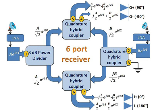
Figure 2 Six port network with I/Q signals at its output.
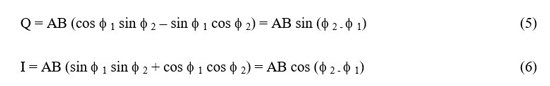
Assume the incident complex signals at Ports 1 and 2 to be Aejφ1 and Bejφ2 respectively. A, B are the magnitudes and φ1, φ2 are the incident phases. The superimposed signals at the four output ports of the six port network are shown. The following equations show the baseband signals at the output of power detectors. These are achieved by taking the square of the magnitude of the complex output signals at the four output ports assuming ideal square law detectors.

The quadrature and in-phase pairs (Q+, Q- & I+, I-) are then fed to differential amplifiers to generate quadrature and in-phase signals respectively. Sum and difference trigonometric identities are applied to extract the quadrature sine and in-phase cosine components of the incident signal complex ratio.
The phase difference (Δφ = φ 2 - φ 1) between the two complex signals Aejφ1 and Bejφ2 can be easily computed using the following expression:

The relationship between the phase difference and the AOA (θ) can be found as:

where L is the distance between two antenna elements and θ is the angle of incidence which can be found using Equations 7 and 8.

Hence, in a direction of arrival (DOA) detection system, the six port network acts like a high resolution phase comparator extracting the I/Q components from the two incident signals. These I/Q signals are then digitized and used in the DSP domain to calculate the angle of arrival. Determining the distance between antenna elements requires a tradeoff between unambiguous FOV and angular resolution/accuracy. It is chosen according to the specific application or in some cases dual baselines are used to achieve both.
APPLICATIONS
The six port network has been one of the biggest innovations in RF and microwave technology in the last decade with numerous applications (see Figure 3). Initially, it was used in portable vector network analyzers9 and reflectometers; however it has recently been used in industrial applications such as precise direction finding and ranging.7 In the field of communications, a six port homodyne receiver architecture can be utilized for direct up conversion/down conversion and modulation/demodulation. It can also be used in 5 G to support ultra high data rates.10 Six port networks have direct applications in optical coherent receivers at extremely high frequencies where the design of conventional architectures becomes very complex. In medical science, vibration and remote heartbeat/respiratory rate sensing have been achieved with the six port’s precise phase resolution.11 Wide applicability is possible because of its numerous advantages, including:
- High phase resolution.
- Absence of phase noise as no LO is required.
- Only passive RF components are used.
- Low size, weight, power and cost (SWaP-C).
- Good performance at high frequencies (microwave and mmwave bands) providing high data rates suitable for ultra-wideband applications.
- 6 port RF front end can be calibrated.
However, there are design tradeoffs that must be considered:
- High insertion loss results in reduced overall dynamic range. It is dependent on having a high gain LNA stage.
- Amplitude and phase imbalances in the transmission coefficients of a six port network result in I/Q gain and phase errors, which must be compensated. Hence, I/Q gain and phase equalization is done by calibration at the DSP level.
- Diode power detectors are nonlinear devices and contribute additional errors; however these can also be compensated through calibration at the DSP level.
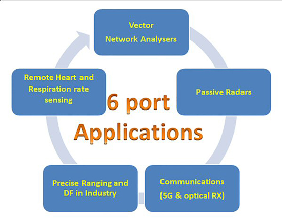
Figure 3 Multidisciplinary applications of six port network.
TOPOLOGIES AND DESIGN TECHNIQUES
A comprehensive survey (see Table 1) focuses on six port network design techniques. Over the years, researchers have used different subcomponents and design methodologies to achieve relative quadrature phase shifts at the four output ports, the signature of a six port network. This survey focuses particularly on broadband designs that can support multimode and multiband applications and analyzes them based on relevant parameters such as operating bandwidth, design complexity, layers, reflection and transmission coefficients (both simulated and measured), phase performance and dimensions. The techniques reviewed are categorized by the following design topologies:
- Three quadrature hybrid couplers (QHCs) & in- phase/out-of-phase power divider (PD).
- Four PDs & 90 degree phase shifters.
- Four QHCs & 90 degree phase shifter.
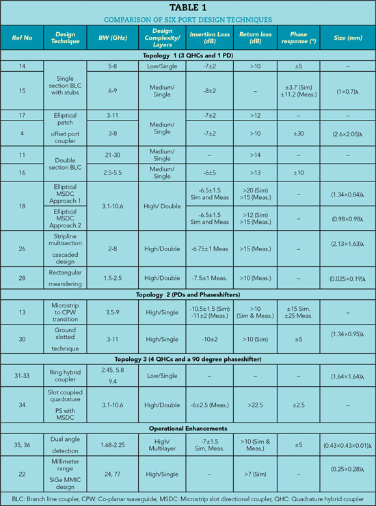
Figure 4 is a classification taxonomy that groups each technique by basic topology, single/double layer design and prominent design feature. A separate categorization for operational enhancements in six port DF designs is included and discussed later.
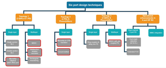
Figure 4 Six port design techniques classification tree. UWB design techniques are outlined in red.
Topology 1 (Three QHCs and one PD)
Topology 1 consisting of three couplers and a divider is the one most widely used. This topology provides the minimum insertion loss (6 dB theoretical) as the input signal passes through only two components. The basic setup consists of two RF inputs feeding 2 LNAs (for extending dynamic range), then the six port network followed by four power detectors feeding into two differential amplifiers to generate the I/Q signals for phase detection. Using this architecture, six ports have been designed in single (see Figure 5) and multilayers (see Figure 6).