
Three of the goals for 5G mobile communications networks are to increase data capacity, decrease latency and connect many more devices. mmWave frequencies with large channel bandwidths are being used to help meet these needs. Indeed, release 15 of the 3GPP 5G specification includes frequencies in the 28 and 38 GHz bands. Drawbacks of these higher frequencies are increased path loss in clear air, in air with precipitation and in environments with higher reflectivity - especially with larger cells outside of dense urban environments.1
Fortunately, the shorter mmWave wavelengths enable more directional antennas in both the base station and user equipment (UE) than is practical at lower frequencies. Antenna arrays for which the radiation pattern can be steered are particularly interesting because higher gain in the desired direction makes up for some of the added path loss, and the narrower beamwidth can reduce same-cell interference. At mmWave, arrays become more practical, even for a mobile phone.2
A significant metric for the performance of a mobile phone antenna is the gain in the direction of the base station. Since the orientation of a phone and direction toward the tower can vary greatly, the phone should to be able to point its maximum gain in any direction. Hence, characterizing the ability of an antenna system to accomplish this is an important metric; one way to do this is predicting or measuring the effective or equivalent isotropic radiated power (EIRP) over all possible directions.
EIRP AND CDF
EIRP, which is a function of direction, is the gain of a transmitting antenna in that direction multiplied by the power delivered to the antenna from the transmitter.3 EIRP can be thought of as the equivalent power required to be delivered to an isotropic antenna to produce the same signal level. For example, if an antenna is driven by 2 mW (3 dBm) from the transmitter and the antenna has 5 dB gain in a given direction, the EIRP in that direction is 8 dBm; the signal in that direction would be the same as if the antenna were isotropic and driven with an 8 dBm signal.
Antenna gain, G, and EIRP, E, are usually expressed as a function of direction, i.e., G(θ,φ) and E(θ,φ). For practical antennas, gain and EIRP are typically continuous functions with minimum and maximum values:
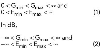
For an ideal isotropic antenna, Gmin = Gmax and Emin = Emax.
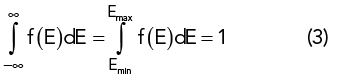
We can define a probability density function, f (E(θ,φ)), over all directions (0 ≤ θ ≤ , 0 ≤ φ < 2π) as
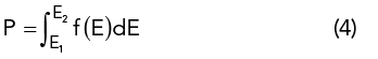
The probability over all directions of the EIRP being between any two values E1 and E2 (inclusive) is
In a typical polar 3D gain or EIRP plot, the magnitude at each θ and φ is plotted as a radius from the origin. For this type of plot, the EIRP of an antenna system will be contained in the closed region between a sphere of radius Emin centered on the origin and an equal or larger sphere centered on the origin of radius Emax.
A cumulative distribution function (CDF) or, simply, the distribution function of the probability density function f (x) is
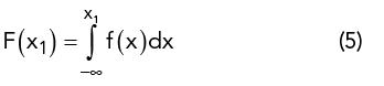
and gives the probability that x ≤ x1.4
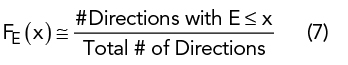
For the EIRP probability density function f (E), the corresponding CDF, FE(x), gives the probability that the EIRP will be ≤ x:
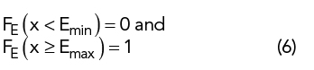
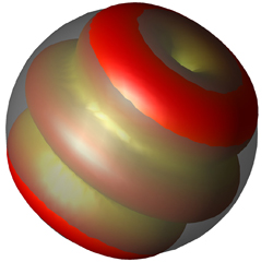
Figure 1 Realized gain CDF at the 3 λ/2 resonance of a 76 mm printed circuit dipole.

Figure 2 8 x 8 patch antenna array on a 52.5 mm x 52.5 mm substrate.
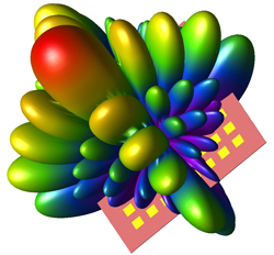
Figure 3 Realized gain of the 8 x 8 patch, fed for maximum gain normal to the plane of the patches.
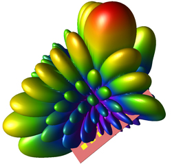
Figure 4 Realized gain of the 8 x 8 patch, fed for maximum gain at θ = 37 degrees and φ = 90 degrees.
For Emin ≤ x ≤ Emax, FE(x) gives the fraction of all possible directions (i.e., fraction of 4π steradians) for which E ≤ x and (1 − FE) gives the fraction for which E > x, i.e., the fraction of a polar plot of E which is “poking out” of a sphere of radius x. For example, Figure 1 shows a sphere representing the realized gain of the 3λ/2 resonance of a 76 mm printed circuit dipole, showing a magnitude of 2 dBi. Approximately 10 percent of the directions have gain more than 2 dBi; in this case, F(2 dBi) ≅ 0.9, so about 90 percent of the gain pattern is contained within the sphere.
When the EIRP over the sphere is sampled at a finite number of directions, such as in a measurement or simulation, the CDF can be approximated by
Patch Array
To illustrate, the CDF of the EIRP will be calculated for a 64 element patch array antenna at 28 GHz.5 All simulations and processing are performed using XFdtd®.6 The geometry is an 8x8 element patch array on a 52.5 mm x 52.5 mm x 0.254 mm substrate with a ground plane (see Figure 2). The electrical parameters of the substrate are εr = 2.2 and loss tangent = 0.0009. This example is restricted to the antenna array structure to illustrate the method. In practice, the antenna would be evaluated by itself in the initial stages of the design, then simulated in a more complex environment, including the complete mobile phone geometry and, possibly, other arrays added for better diversity of coverage and polarization.
The realized gain patterns for maximum signal in two directions are shown in Figures 3 and 4. Figure 3 shows the radiation pattern of the array with all elements fed in phase, so the principal lobe is perpendicular to the plane of the antenna, i.e., θ = 90 degrees. The maximum gain is 24.2 dBi. Figure 4 shows the radiation pattern of the array with all elements fed with a phase taper across the 2D array, so the principle lobe is along the direction θ = 37 degrees and θ = 90 degrees. The maximum realized gain in this case is 23 dBi. A single element of this array will have reduced gain toward the back (i.e., the ground plane side), so the array will not have gain as high in that hemisphere. Also, integrating the array into a phone will yield additional effects on the radiation pattern.
Determining how well the array performs in every direction is useful. What is the distribution of EIRP over the sphere? Since this is a simulation, it is straightforward to characterize the maximum gain in many directions. However, to capture the many variations we expect on the gain pattern due to the geometry, the number of sample directions needs to be large. The CDF of EIRP provides a useful, one-dimensional function to characterize the array’s performance over all possible directions.
The far zone radiation due to each element in the array is computed for the full geometry. These patterns can be combined in post processing to compute the gain and EIRP for any combination of elements, enabling the power and phase delivered to each element to be set independently. To compute the CDF, the phase of each element in the array is adjusted to provide maximum EIRP in each of a suitably large number of sample directions representing the sphere of all possible directions. The CDF of EIRP function can then be computed from Equation 7.
A CDF of the EIRP for the full 8x8 element array and several subarray combinations is shown in Figure 5. For all cases, the transmitter is assumed to have a power of 23 dBm, which is typical for a mobile phone. For the 8x8 element case, the EIRP is about 37 dBm at a fractional area of 0.5, which means that half of the directions have an EIRP larger than 37 dBm. For the 4x4 subarray, elements from one quarter of the array are used to determine the CDF of EIRP. This CDF curve has a similar shape but shifted down in EIRP, as expected for an array with one quarter as many elements. Elements from one corner of the array are used in the CDF for the 2x2 subarray, and the CDF has a similar drop in EIRP compared to the 4x4 case. Finally, a 1x8 arrangement of elements from one side of the array shows the EIRP lies between the 2x2 and 4x4 element subarrays, again as expected. This type of array might be used in a mobile phone, with arrays on two sides to provide more complete coverage.
As seen from these curves, about half of the possible directions have significantly lower EIRP due to the ground plane, which emulates the placement of the array in a phone. One way to provide broader coverage is to place multiple antenna arrays in the device, such as on either edge of the mobile phone, as mentioned. By properly combining the distributions, the CDF of the EIRP can be used to estimate the ability of multiple arrays or subarrays to work in combination to provide higher EIRP in all directions and reduce blind spots. This measure can also be evaluated using multiple antennas for diversity and coverage in all polarizations.
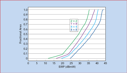
Figure 5 EIRP CDFs for the full 8 x 8 element patch array and several subarrays.
Conclusion
Steerable array antennas are of significant interest to help meet the goals of 5G mobile communications. At mmWave frequencies, such as 28 and 38 GHz, fairly large and directional arrays become practical for relatively small devices such as mobile phones; however, these frequencies have higher path loss than at microwave frequencies which have been used in previous generations. For a given power level, the ability of antenna arrays to control the direction of maximum radiation will allow for much better EIRP in the direction of communications.
The CDF of EIRP, computed from a suitably large number of sample directions, may be used to assess the directionality and effective coverage of an antenna array. The article used a simple example of an 8x8 patch antenna array to demonstrate the usefulness of the CDF of EIRP to characterize the ability of an array to provide good EIRP in all directions.
References
- T. S. Rappaport, S. Sun, R. Mayzus, H. Zhao, Y. Azar, K. Wang, G. N. Wong, J. K. Schulz, M. Samimi and F. Gutierrez, “Millimeter Wave Mobile Communications for 5G Cellular: It Will Work!,” IEEE Access, 2013, pp. 1:335–349.
- W. Hong, K. Baek and S. Ko, “Millimeter-Wave 5G Antennas for Smart-Phones: Overview and Experimental Demonstration,” IEEE Transactions on Antennas and Propagation, Vol. 65, No. 12, December 2017, pp. 6250–6261.
- “Definitions of Terms for Antennas,” IEEE Standard 145-2013, 2013.
- W. Feller, “An Introduction to Probability Theory and Its Applications, Volume I,” John Wiley & Sons Inc., 1959, p. 168.
- Remcom, “Beamforming for an 8x8 Planar Phased Patch Antenna Array for 5G at 28 GHz,” Microwave Journal, January 11, 2019, www.microwavejournal.com/articles/31634.
- “Xfdtd,” Remcom Inc., March 2019.