
Automobiles are technologically sophisticated and connected. Newer vehicles include advanced sensor technologies to improve safety, and manufacturers continue to incorporate more sensors to provide real-time data from the external environment to the driver and the car’s control systems. These sensors enable many safety features: early warning, corrective steering and braking systems encompassing lane departure, adaptive cruise control, autonomous emergency braking and blind-spot detection.
Nevertheless, new solutions are needed to increase safety and achieve truly autonomous driving - at level 5 of the Society of Automotive Engineers capability scale. Recent research and investment have targeted sensor technologies such as LiDAR and enhanced passive imaging, i.e., cameras. Some industry pundits have posted that autonomous driving vehicles will include a very rich portfolio of these optical sensors on the path to levels 4 and 5. Perhaps counterintuitively, radar, which has been a mainstay in vehicles for some years, has not achieved the same fanfare as LiDAR, since radar already offers a stable, all weather, cost-effective sensor to help enable the current levels of autonomy and safety. On the other hand, compared to optical technologies, one radar weakness is angular resolution, defined as the minimum angle the radar can distinguish and separate two equally large targets at the same range.
This article discusses the application of new technology and advanced signal processing that will enable radar to do much more. First, basic concepts about angular resolution and antenna patterns in radar will be described. Then, Uhnder’s development of digital code modulation (DCM) radar with coherent MIMO technology will be discussed, outlining its advantages compared to state-of-the-art radar technology.
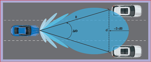
Figure 1 The angular resolution of a radar is determined by the −3 dB beamwidth of the main lobe.
ANGULAR RESOLUTION
A radar’s angular resolution is directly proportional to the effective area of its antenna array, typically referred to as the antenna aperture. As shown in Figure 1, when defining angular resolution, the main lobe half-power points (−3 dB) of an antenna’s radiation pattern are normally specified as the limits of the antenna’s beamwidth. Two identical targets at the same distance are resolved in angle if they are separated by more than the −3 dB beamwidth. In the common driving scenario shown in Figure 1, to distinguish two identical cars at a slant range, R, from the sensor and spaced at distance, d, from each other, the required angular resolution is defined by the following expression:

For example, if d = 4 m and R = 125 m, an antenna beamwidth of 1.8 degrees is required to achieve this angular resolution. This case exemplifies the scenario where the vehicle needs to decide whether the lane between the two cars is occupied. It is a challenging requirement for currently deployed automotive radars, which achieve a few degrees of angular resolution at the expense of having a very narrow field of view (FOV) and ambiguity in angles (i.e., allowing targets from multiple angles to fold onto each other). Fortunately, that issue can be solved with a coherent MIMO radar.
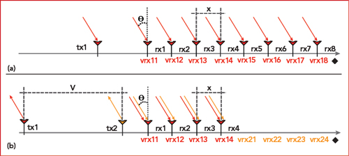
Figure 2 Standard (a) and MIMO (b) antenna arrays to achieve eight virtual receivers.
MIMO RADAR
To understand the MIMO radar, refer to Figure 2a, which shows the physical antenna configuration for a quasi-monostatic radar. A single transmit (Tx) and eight receive (Rx) antennas provide closely located channels, forming a single-input-multiple-output (SIMO) radar. The distance x between the Rx antennas is chosen to achieve the desired unambiguous FOV:
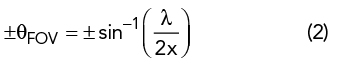
where λ is the wavelength. This unambiguous FOV defines the angular region within which the target directions are uniquely identified, assuming all targets are within this region. Targets beyond this region will appear to fold into it and cannot be distinguished from the targets within the region. The FOV will be maximum (±90 degrees) when x = λ/2. That is the preferred choice to avoid ambiguities when estimating target directions. When Tx1 sends a waveform, the eight Rx antennas will receive an attenuated copy of the signal, shifted in phase by a constant Φ between each of the eight Rx antennas. The phase shift is computed from:
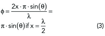
where θ is the angle of arrival or the target’s direction. From the receiving antenna Rx1 to Rx8, the total phase shift will be 7Φ.
A completely equivalent result can be achieved with a thin MIMO array, shown in Figure 2b, which is formed with two Tx antennas separated by 2λ and four Rx antennas separated by λ/2. In this case, each Rx antenna will receive a pair of waveforms, Tx1 and Tx2. For the Rx channels to separate the signals coming from the two Tx antennas, the transmitters need to generate orthogonal waveforms. After matched filtering of the two Tx waveforms, to separate the received signals from the two transmitters at each receive antenna, eight virtual receivers (VRx) are created (i.e., 2 x 4 = 8), which have equivalent phase shifts as the configuration of Figure 2a.
The single and dual Tx configurations provide equivalent angular resolution. However, the MIMO architecture uses only six antennas, compared to nine with the SIMO design. The reduction in hardware with the MIMO version is a significant advantage.
This same principle, on an entirely different scale, was used in space research to create the first direct images of a black hole. Astronomers created a “virtual telescope,” a planet-scale array comprising eight radio telescopes, to increase the antenna aperture and improve angular resolution down to 20 μarcseconds - 3 million times sharper than 20/20 vision.1
An antenna array, like those in Figure 2, will have a beamwidth given by:
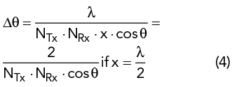
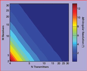
Figure 3 Angular resolution for a MIMO radar vs. number of Rx and Tx channels.
where NTx and NRx are the number of Tx and Rx antennas, respectively. Both arrays have an angular resolution of approximately 14 degrees. For comparison, Figure 3 shows the achievable angular resolution at boresight (θ = 0) versus the number of Rx and Tx antennas. From the figure, an angular resolution of 1.8 degrees can be achieved with a configuration combining eight Rx and eight Tx antennas.