
An integrated, high performance, 140 GHz frequency-modulated continuous wave (FMCW) radar system enables the detection of minute motion, offering utility for various applications. Its main features are described in this article, including transceiver characterization and measurements of vital signs using a 2x2 MIMO radar assembly.
Since the introduction of the first radar systems in the early 1930s, radar technology has evolved significantly. During this time, researchers have reduced the size, power consumption and cost dramatically, while increasing resolution and enhancing the algorithmic computational capabilities. Development and advances in IC technology have enabled a class of low-power and short-range mmWave radars with carrier frequencies in the 30 to 300 GHz range (10 to 1 mm wavelength), adding to the mass of wireless applications pervading society. Today, radars are embedded in a number of cars, as parking aids or for safety, detecting pedestrians, other road users and objects at a few meters.
These high frequency radars with small form factors can be integrated almost invisibly in numerous devices, to enable a broad range of smart and intuitive applications, such as building security (e.g., people counting and intruder detection), remote health monitoring of automobile drivers, monitoring the vital signs of patients and gesture recognition for intuitive man-machine interaction. The number of use cases will imminently grow as radar systems offer finer range resolution, smaller footprint, higher energy efficiency and lower cost.
A MULTITUDE OF FLAVORS
Although all radar systems follow the same basic principle, their various implementations determine the cost, size, power consumption and capability. Radars can differ by the frequency of the carrier (e.g., 2.4, 8, 60, 79, 140 GHz), bandwidth, type of carrier modulation (e.g., frequency or phase) and pulsed or continuous wave (CW). By necessity, small radars with high resolution operate at high carrier frequencies with wide bandwidth. As resolution is inversely proportional to bandwidth, radar systems operating above 100 GHz can offer very broadband operation, which enables fine range resolution. A Doppler shift is observed as a change in frequency of the wave reflected from a target, when the source and target are moving closer together or further apart. This shift can be measured more precisely at higher frequencies to provide a more exact determination of a target’s velocity.
In time, data from multiple sensors - which may add LiDAR, hyperspectral imagers, infrared cameras and ultrasonic sensors to radar - will be merged on a common platform, each offering advantages and having limitations. Radar technology is an environmentally robust solution and can serve as an alternative to optical image sensors when privacy concerns or regulations prohibit using cameras. Supplementing the development of radar sensor technology, advances in physical pattern recognition are driving advanced machine learning techniques to classify objects or gestures using radar Doppler signatures.
140 GHz FMCW RADAR TRANSCEIVER IC
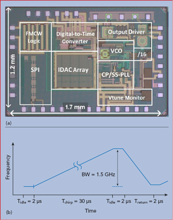
Figure 1 16 GHz FMCW PLL IC (a) and chirp modulation response (b).
Targeting vital sign detection and gesture recognition, imec has developed a 140 GHz FMCW radar transceiver with on-chip antennas. The radar operates over a range from 0.15 to 10 m and has 11 mm range resolution, achieved with 13 GHz of RF bandwidth centered at 145 GHz. The transceiver IC is fabricated with a production 28 nm bulk CMOS technology, which enables a low-cost solution.
The main building block of the radar is an integrated transceiver featuring on-chip antennas and a sub-sampling digital phase-locked loop (PLL), which forms the FMCW chirp generator. Antennas integrated on the same chip couple with each other, resulting in leakage between the transmit (Tx) and receive (Rx) paths; however, the radar features on-chip leakage cancellation in the receiver to circumvent this effect, which can result in gain compression and DC offsets. The radar receiver measures the difference between the frequency of the reflected and transmitted RF chirps. This frequency difference is translated into the MHz range, making amplification, filtering and analog-to-digital conversion much easier than with other radar waveforms (e.g., phase-modulated CW).
The PLL generates a frequency modulated CW signal, where the carrier frequency is modulated over a wide bandwidth using a linear sawtooth waveform. The repetition rate of the modulating sawtooth is known as the chirp rate. Imec has developed and characterized a 16 GHz, fast chirping PLL fabricated with a 28 nm bulk CMOS process (see Figure 1a). This PLL can operate both in a classical mode as well as a divider-less sub-sampling mode, offering flexibility and high performance. The PLL achieves a wide chirp bandwidth of 1.5 GHz in only a 30 μs chirp period, allowing fast sawtooth frequency modulation (see Figure 1b).
Multiple transceiver ICs were used to create a 2x2 MIMO radar, augmenting the range and speed detection capabilities of a single-input-single-output radar. MIMO increases the azimuth angular resolution, providing additional information to resolve target orientation.
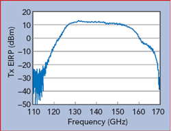
Figure 2 Transmitter EIRP.
In the MIMO configuration, a central 16 GHz chirp signal is distributed to multiple Tx inputs. The signal is up-converted to 144 GHz using a cascade of two frequency triplers, after which it is amplified and transmitted via the on-chip antennas. The radiated chirp is reflected by targets broadside to the antennas and captured by the on-chip receiver. The reflected signal is amplified in the receiver and compared with a replica of the initial chirp signal, using a mixer. The delay of the received signal, corresponding to the time-of-flight to the target and back, results in an instantaneous frequency offset compared to the reference chirp. The greater the distance to the target, the greater the relative frequency shift and the range of the target is obtained from the frequency of the down-converted signal. The analog output from the receiver is converted to a digital signal, enabling signal processing to extract the range and speed.
The transmitter is characterized by its effective isotropic radiated power (EIRP). For the integrated 140 GHz prototype, the measured EIRP is as high as 11 dBm and has a 3 dB bandwidth from 127 to 154 GHz (see Figure 2). This is the highest recorded EIRP in D-Band for a single integrated transceiver compared to currently published state-of-the-art ICs (see Table 1). The receiver’s performance is characterized by its noise figure and conversion gain: 8 and 84 dB, respectively (see Figure 3). The total power consumption of the radar transceiver IC is less than 500 mW.
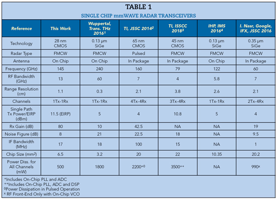
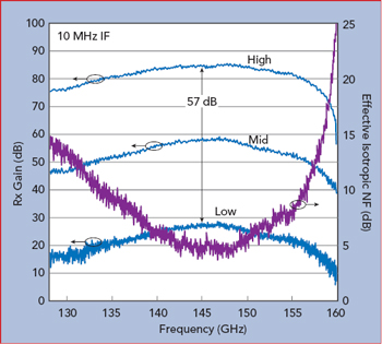
Figure 3 Receiver gain and effective isotropic noise figure.
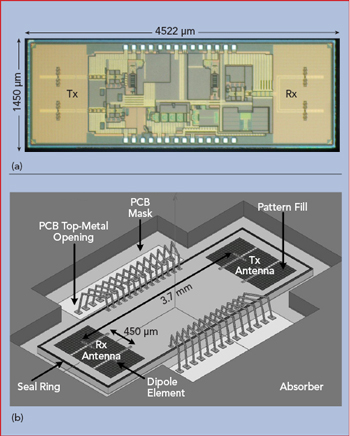
Figure 4 Transceiver IC (a) and packaging (b), showing the Rx and Tx antennas integrated on opposite sides of the IC.
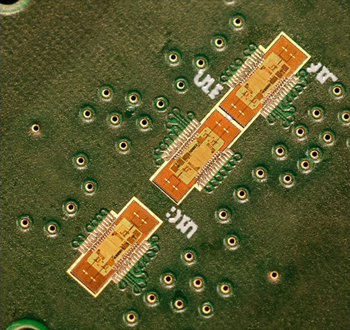
Figure 5 MIMO radar board with three transceiver ICs.
Radars with frequencies below 100 GHz require large off-chip antennas, which are usually fabricated on high frequency laminates and attached to the IC via flip-chip or wire bond interfaces. Developing and implementing these complex antenna-on-package modules significantly contributes to the cost and size of the final radar system. However, the higher the frequency of the carrier - the smaller its wavelength - the more the size of the antenna element is reduced. For carrier frequencies above 100 GHz, the antenna is sufficiently small that it can be integrated on the radar chip. This antenna-on-chip solution offers clear size and cost advantages compared to off-chip antennas on printed circuit boards (PCB). When integrated on-chip, there is no need for mmWave transitions between the IC and PCB that ultimately degrade bandwidth and signal strength. In this design, the antenna elements were integrated into the passivation layer of the transceiver, with the Tx and Rx antennas 2 mm apart to minimize crosstalk (see Figure 4).
For many applications, including gesture recognition, high angular resolution is needed to capture gestures in three dimensions. This can be accomplished with MIMO radar, as they transmit mutually orthogonal signals from multiple Tx antennas, which are then extracted from each of the Rx antennas. Imec has demonstrated a 1x4 virtual array with three transceiver ICs, including two transmitters and two receivers, resulting in a 2x2 MIMO assembly shown in Figure 5. The configuration is called “1x4 virtual” because the angular resolution corresponds to the resolution obtained by the four elements in a row. In this configuration, the central chirp signal is distributed to the separate transceiver chips on a PCB. Using the super-resolution MUSIC algorithm, a fine angular resolution of 7.5 degrees is achieved with a complete MIMO radar form factor of only a few square centimeters.
VITAL SIGN DETECTION AND GESTURE RECOGNITION
Two main applications are envisioned for the 140 GHz MIMO radar: vital sign detection and gesture recognition.
The feasibility of detecting vital signs in real-time, including monitoring heart rate and breathing, have been demonstrated. The 1x4 MIMO radar captured the 1 and 5 Hz beats of a “reference heart” - a speaker diaphragm with 1 mm displacement - as shown in Figure 6a. In a second experiment, the feasibility of measuring micro-skin motion in real-time, which reflects a person’s respiration and heartbeat, was demonstrated (see Figure 6b). In the future, greater processing capability will enable more accurate distinctions between heartbeat and respiration.
A portable 1x4 MIMO radar demonstrator is currently being built to measure vital signs in real-time. To capture gestures and motion, the radar must have high angular resolution, which is achieved with larger MIMO arrays. A 4x4 virtual MIMO radar, realized by one row and one column of four transceiver ICs each, is currently being developed and will be complemented with additional processing capabilities for micro-Doppler information and machine learning techniques. Machine learning will train the system using classified data to recognize the Doppler signatures of moving objects.
SUMMARY
An extremely compact, fully integrated 140 GHz FMCW radar transceiver in 28 nm CMOS has been demonstrated. Centered at 145 GHz and up-converted from a 16 GHz PLL chirp signal, an RF bandwidth of 13 GHz yields 11 mm range resolution. The IC contains Tx and Rx signal paths and integrated antennas. For the transmitter, a record EIRP of 11 dBm from a single element was measured, while the receiver achieved a noise figure and conversion gain of 8 and 84 dB, respectively. In a 2x2 or 1x4 virtual MIMO configuration, fine angular resolution was achieved. These features enable the radar to detect vital signs and gestures. Imec is currently building portable demonstrators to further show the capability of its 140 GHz MIMO radar systems.
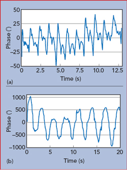
Figure 6 MIMO radar vital sign measurements: reference heartbeat (a) and skin motion reflecting heartbeat and respiration (b).
Imec is also developing other compact and low-cost radar sensing solutions for IoT applications, including 8, 60 and 79 GHz CMOS-based radars. The ICs are designed to achieve state-of-the-art performance while avoiding “specialty” semiconductor technologies.
ACKNOWLEDGMENT
The authors thank Panasonic and Sony for their support.
References
- J. Grzyb et al., “A 210–270-GHz Circularly polarized FMCW Radar with a Singlelens-Coupled SiGe HBT Chip,” IEEE Trans. THz Sci. Technol., Vol. 6, 2016, pp. 771–783.
- B. Ginsburg et al., “A 160 GHz Pulsed Radar in 65nm CMOS,” IEEE JSSC., Vol. 49, No. 4, April 2014, pp. 984–995.
- B. Ginsburg et al., “A Multimode 76-to-81GHz Automotive Radar Transceiverwith Autonomous Monitoring,” ISSCC, 2018, pp. 158–159.
- H.J. Ng et al., “Miniaturized 122 GHz System-on-Chip Radar Sensor with On-Chip Antennas Utilizing a Novel Antenna Design Approach,” IEEE MTT-S Int. Microwave Symp., 2016.