
Base station antennas have long been a critical component of wireless cellular communication systems. One of the most important performance parameters for many designs has been passive intermodulation (PIM). PIM can negatively affect receiver sensitivity, decreasing system capacity and data rates, leading to increased rates of dropped calls. While not a critical parameter in all systems, PIM is typically a design consideration in CDMA, LTE and 5G FDD systems.
In an antenna, PIM is the result of two higher power signal tones mixing, caused by various nonlinearities that occur within the system. If the two signals are f1 and f2, the intermodulation occurs at 2f1−f2 and 2f2−f1 (third-order products), 3f1− 2f2 and 3f2− 2f1 (fifth-order products) and so on (see Figure 1). If the third-order or other products fall within the receive band, the PIM can prevent the receiver from detecting legitimate signals.
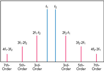
Figure 1 Passive intermodulation products.
PIM values are usually expressed in dBc, the power of the intermodulation products in dB below the two fundamental signals. Testing involves two closely spaced tones of 20 W (43 dBm), so measuring third-order intermodulation products at −110 dBm equates to a PIM of −153 dBc. While −153 dBc was once considered good for PIM-sensitive applications, increasingly systems are requiring −160 dBc or better. Because of the noise levels of measurement systems, PIM levels much better than −165 dBc can be hard to verify.
There are various potential sources of PIM within an antenna system: interfaces between different metals, loose connectors, poor solder joints and contamination from dirt, dust and especially traces of ferromagnetic materials. Printed circuit board (PCB) technology is often used in antennas, whether as radiating elements or feed networks, and the use is increasing. For PCB antennas, while PIM is a property of the complete circuit, the choice of RF circuit material has an impact. It is well understood that the roughness of the interface between the copper foil and the dielectric material significantly affects PIM. The ideal circuit material has low loss with a tight control of dielectric constant and, most importantly, a consistently smooth copper interface achieved with a high level of copper foil adhesion. Figure 2 illustrates the relationship between PIM and copper surface roughness.
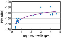
Figure 2 PIM increases with copper surface roughness.
Rogers Corp. is an industry leader for high performance RF/microwave circuit materials. For base station antenna applications, Rogers typically offers the AD Series™ PTFE-based laminates and the RO4500™ and RO4700™ Series hydrocarbon laminates. The RO4000® materials are typically used where there is a greater degree of integration, for multilayer PCBs or for antenna elements where a greater degree of physical rigidity is required. However, for the best electrical performance, the AD Series laminates have the lowest dissipation factor for the lowest dielectric losses, as well as the widest range of dielectric constants.
While all these materials are available in low PIM versions, Rogers has introduced its newest, industry-leading low PIM products: the IM Series™ laminates.
The IM™ system is now an option for AD300D™, AD255C™ and DiClad880® antenna-grade laminates. These products use an ultra-smooth electrodeposited copper foil—with an Rq of just 0.5 μm (measured with the non-contact interferometry method)—while maintaining excellent adhesion to the substrate surface (see Figure 3).
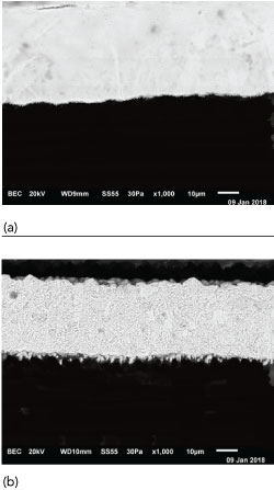
Figure 3 0.5 μm IM copper (a) vs. reverse treat 1.0 μm electrodeposited copper (b).
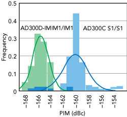
Figure 4 PIM distribution of AD300D- IM vs. AD300C with S1 copper.
The PIM performance of these materials with the IM cladding is typically −165 dBc, measured using two 43 dBm swept tones. Yet, the real benefit of the new materials is not only low PIM, rather consistent and tightly controlled low PIM. With the introduction of new equipment and new quality control checks, Rogers is able to deliver a material which demonstrates much lower variation in PIM. The primary benefit of having consistently low PIM, in addition to meeting the PIM specification, is greater production yield and reduced scrap during antenna manufacturing. Figure 4 shows a significant 6 dB average improvement in PIM compared to the previous generation AD300CTM laminate with the more tightly controlled distribution of PIM.
Rogers’ specialty materials are engineered and manufactured to meet the needs of today’s RF engineers. With the introduction of the new IM series of RF laminates, Rogers continues to produce leading products that enable antenna designers to meet the toughest PIM specifications while maximizing production yields.
Rogers Corp.
Chandler, Ariz.
www.rogerscorp.com