
NEW FEATURES
The emerging mmWave applications and attendant considerations for coaxial cables are driving innovation in the design and manufacturing of next-generation coaxial assemblies. Some of these innovations involve adopting coaxial cable manufacturing methods and techniques from SATCOM, aerospace and military applications. Other enhancements are designed to improve ease-of-use, increase longevity and allow for more standard solutions, rather than expensive custom designs.
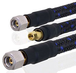
Figure 6 New high-performance mmWave coaxial cable assemblies use military-grade manufacturing techniques and armoring to ensure reliable performance from the laboratory to the field.
For example, common metals used in precision mmWave connectors include passivated stainless steel and beryllium copper plated with both nickel and gold, where the last plating step is gold. The beryllium copper provides dimensional stability over temperature, the nickel is a necessary layer to enable gold plating and the gold surface conductor provides high surface quality with good conductivity and better corrosion resistance than copper, aluminum or silver. A passivated stainless steel coupling nut and outer body provide a durable connector body with improved mate-demate cycles and corrosion resistance (see Figure 6).
Cable armoring for mmWave vector network analyzer (VNA) test cables is also a new technique, adapted from military and aerospace applications. A coaxial test cable designed to operate to 110 GHz is roughly 0.25 in. diameter, with very thin layers of conductors and dielectric. As the coaxial structure of these cables can easily be damaged, even when carefully handled and in laboratory conditions, cable armor improves durability. Methods include additional foil and braided metal layers and light armoring with rugged synthetics such as Nomex®, crush members, external ruggedized metal armor and additional inner jackets. Though these methods of cable protection increase the size and weight of a coaxial cable assembly, they improve the rigidity of a cable while maintaining its flexibility. Where rigid and semi-rigid coaxial cable must be formed to the exact dimensions of the end application and cannot be reformed without damaging the cables, flexible coaxial assemblies with armoring can undergo repeated flexure, often with better phase and amplitude stability than un-armored coaxial assemblies.
These design techniques can improve the performance of mmWave coaxial cable assemblies and extend life-span compared to other flexible coaxial assembly designs. These techniques do increase the cost of the assembly and often require longer lead times to manufacture. As the model for using mmWave coaxial cables and connectors changes to meet emerging trends and applications, the method of sourcing the coaxial assemblies also needs to change.
SUMMARY
Military, aerospace and SATCOM technologies and emerging applications from new markets are changing the way mmWave coaxial cables and connectors are designed, sourced and employed. Beyond precision VNA testing and use in aerospace communications and radar, mmWave coaxial cable assemblies are now being used in commercial telecommunications and automotive applications. Coaxial cable manufacturers have made strides in recent years to meet these new needs and, by some suppliers, to provide these solutions faster and more seamlessly than in the past. As the 5G, automotive radar, mmWave MMIC, automated testing and high speed data markets continue to grow, so will the need for lower cost, faster lead time and higher performing coaxial cables and connectors.
References
- “FCC Online Table of Frequency Allocations,” www.fcc.gov/oet/spectrum/table/fcctable.pdf.
- R. W. Heath, Jr., “Vehicular Millimeter Wave Communications: Opportunities and Challenges,” www.slideshare.net/ctrutaustin/heath-45522468.
- “Cisco Global Cloud Index: Forecast and Methodology, 2016–2021 White Paper,” www.cisco.com/c/en/us/solutions/collateral/service-provider/global-cloud-index-gci/white-paper-c11-738085.html.
- S. J. Orfanidis, “Chapter 11: Transmission Lines,” Electromagnetic Waves and Antennas, www.ece.rutgers.edu/~orfanidi/ewa/ch11.pdf.
- B. C. Wadell, “Transmission Line Design Handbook,” Artech House, 1991, Table 9.3.2, p. 446.
- “CRC Handbook of Chemistry and Physics,” 1st Student Edition, 1998, p F-88.