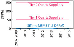
Figure 1 MEMS vs. quartz oscillator DPPM.
The unabated demand for mobile services and increased bandwidth is driving the need for network densification in urban environments. The deployment of small cells is helping to address this growing demand. Small cells, as the name implies, are smaller, lower power base stations with output power in the range of 200 mW to 10 W and coverage from 10s of m to 2 km. According to the Small Cell Forum, 14 million small cells have been deployed as of May 2016, and over 5 million are expected to ship in 2017. China Mobile is leading the way, with an expected tender for 1 million units. Small cells will also play an important role in the roll-out of 5G, using the short range of millimeter wave frequencies.
Outdoor small cell deployments pose special challenges because of obvious factors such as weather, which can involve both extreme temperatures and rapid temperature changes, and vibration transients from trains, wind and heavy vehicles. State-of-the-art MEMS oscillator technology is ideally suited to meet these outdoor deployment challenges.
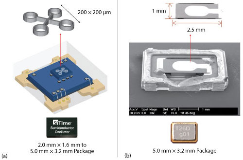
Figure 2 Typical MEMS (a) and quartz (b) oscillator assemblies.
EVOLUTION OF MEMS OSCILLATORS
For over 75 years, quartz oscillators have served the electronics industry in applications that require precise frequencies with part-per-million accuracy. They have served the industry well despite certain intrinsic weaknesses. Because of these weaknesses and the economic scale of the silicon IC infrastructure, all-silicon MEMS timing devices have begun to replace quartz oscillators. In 2006, the first MEMS-based oscillator was released, and it demonstrated superior performance under shock and vibration, as well as the absence of sudden frequency jumps at certain temperatures (i.e., activity dips and micro jumps). Since the initial release of MEMS oscillators, the technology has improved considerably—temperature compensation and the phase-locked loop (PLL) — to reduce jitter and phase noise.
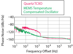
Figure 3 Phase noise of 20 MHz temperature compensated MEMS oscillator and TCXO with 15 Hz to 2 kHz random vibration.
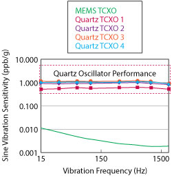
Figure 4 Comparison of vibration sensitivity at 4g acceleration.
Today’s MEMS oscillators are the result of years of technology refinement and millions of dollars in investment. The latest MEMS timing technology delivers low noise/low jitter clocks with unmatched resilience to environmental stresses, including shock, vibration, airflow and fast temperature transients. This performance enables more reliable and higher performance in all applications, including small cells.
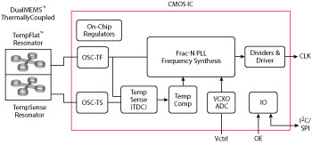
Figure 5 DualMEMS oscillator block diagram.
MEMS Reliability
In MEMS resonator design, the designer has complete control over the lateral shape of the resonator and can control resonant modes. MEMS are designed to be free of spurious mode crossings with the fundamental mode, making them free of resonator-induced activity dips. The MEMS has a single mechanical structure of pure silicon, with a tensile strength of 7 GPa—which is 14× higher than titanium (i.e., 330 to 500 MPa). During oscillation, the resonator moves less than 1 percent of the gap distance between the sidewalls. Acceleration of over 1 million g would be required to force the resonator to contact the sidewall, where g = 9.8 m/s2, the acceleration due to gravity at sea level.
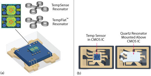
Figure 6 Comparison of MEMS (a) and quartz (b) oscillator assemblies.
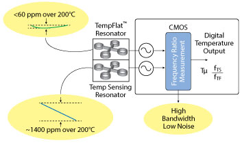
Figure 7 MEMS temperature to digital converter.
During MEMS manufacturing, a proprietary process cleans the resonator and hermetically seals it in a vacuum to eliminate aging mechanisms. This process is the basis for the very high reliability of MEMS oscillators. For example, SiTime has shipped over 625 million MEMS oscillators with no field failures attributable to the MEMS resonator. Figure 1 compares the reliability of MEMS oscillators to quartz oscillators. The MEMS data shows 30× lower defective parts per million (DPPM).
Reliability is an important consideration for any design and is especially vital for equipment deployed outdoors. Better reliability improves the quality of service and reduces maintenance cost and the total cost of ownership.
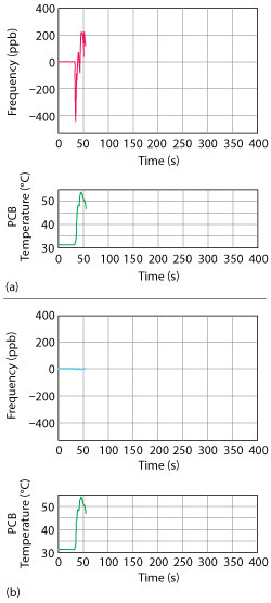
Figure 8 Frequency deviation of a quartz TCXO (a) and temperature compensated MEMS oscillator (b) when subjected to a fast temperature ramp. https://youtu.be/Bttd1f1wo6g
Vibration Performance
MEMS-based oscillators are very resistant to a variety of environmental stresses, including shock and vibration. MEMS resonators have approximately 1000 to 3000× lower mass than quartz resonators (see Figure 2). This means that a force on a MEMS structure from shock or vibration will result in much lower acceleration than its quartz equivalent, within a much lower frequency shift. This benefit is illustrated in Figure 3, which compares the phase noise of a MEMS temperature compensated oscillator to a best-in-class quartz temperature compensated crystal oscillator (TCXO). The random vibration magnitude was 7.5 g root mean square (rms) over a frequency band from 15 Hz to 2 kHz. The MEMS oscillator has approximately 20× lower phase noise in this frequency range, which is a significant benefit to systems facing this type of environmental stress. Maintaining good phase noise performance in the presence of vibration is very important for small cells, helping to eliminate dropped calls and maintain high data throughput.
Another test of vibration sensitivity is the frequency shift per g of sinusoidal acceleration. The most common measure is part per billion (ppb) frequency shift per g of acceleration (ppb/g). Figure 4 compares the vibration sensitivity of a temperature compensated MEMS oscillator to four quartz TCXOs. The sensitivity of the MEMS oscillator ranges from 15 to 150× lower, depending on the vibration frequency. With the MEMS oscillator, no vibration-induced spurs are detected above the random noise floor.
DUAL MEMS OSCILLATOR
Vibration resistance and reliability have been intrinsic advantages of MEMS oscillators since early generations were developed. Recent advances in technology, such as a dual MEMS architecture employed in the Elite Platform MEMS oscillator families from SiTime, provide additional benefits: resilience to fast temperature ramps and low phase noise. Before quantifying these benefits, it will be instructive to provide a brief overview of the dual MEMS architecture to explain how these advantages are achieved. Figure 5 shows a block diagram of the DualMEMS™ oscillator. Shown at the left of the block diagram are the two MEMS that comprise the temperature sensor and resonator. One resonator, the TempSense (TS) resonator, is used as a temperature sensor, exploiting its relatively steep but linear ‐7 ppm/°C frequency vs. temperature slope. The second, which provides a reference clock to the downstream PLL, is designed to have a relatively flat frequency vs. temperature slope and is called the TempFlat™ (TF) resonator. The ratio of frequencies of the TF and TS resonators provides an extremely accurate reading of the resonator temperature, with 30 µK resolution. Another key feature is the tight thermal coupling between the TF and TS resonators, which are fabricated on the same die and separated by only 100 µm. This results in virtually no thermal lag between the TF and TS resonators. Simulations have shown only 52 mK temperature offset between the TF and TS resonators when exposed to heat flux.
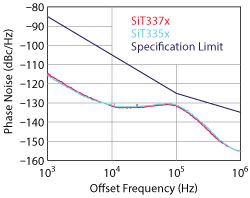
Figure 9 MEMS oscillator phase noise vs. small cell specification for a 122.88 MHz reference clock.
By contrast, the temperature sensor in quartz TCXOs is integrated in an IC that sits below the quartz resonator, on the substrate of the ceramic package (see Figure 6). This spatial separation between the temperature sensor and the resonator results in a thermal lag between the two elements, which introduces significant frequency error when subjected to fast thermal transients.
Another key element of the MEMS temperature compensation architecture is the temperature to digital converter (TDC) (see Figure 7). This circuit block generates an output frequency which is proportional to the ratio of the frequencies generated by the TF and TS resonators. The TDC has a 30 μK temperature resolution and bandwidth to 350 Hz. These features enable excellent phase noise close to the carrier and Allan deviation (ADEV) performance. ADEV measures low frequency jitter and wander. More precisely, ADEV is a two sample deviation of fractional frequency values measured continuously with time. It quantifies how much the average frequency changes over a certain time interval, called the averaging time or tau, and can be specified in a table format or as a plot vs. averaging time. With the TDC, the ADEV is less than 10‐10 with 1 s averaging.
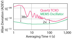
Figure 10 ADEV performance of MEMS and quartz oscillators with airflow.
The high bandwidth of the TDC and the tight thermal coupling between the TF and TS resonators result in minimal frequency error when the temperature compensated MEMS oscillator is subjected to fast temperature transients. Figure 8 shows the performance of the DualMEMS architecture responding to fast thermal transients, compared to a ±50 ppb carrier-grade quartz TCXO. When a heat gun is applied simultaneously to the two oscillators, the quartz TCXO deviates up to 450 ppb from the nominal temperature, exceeding its datasheet specification by 9×. The change of the MEMS oscillator is barely noticeable, well below the specification of 100 ppb. Resilience to rapid temperature transients is important for small cell quality of service during changing environmental conditions.
The fractional-N PLL is another important architectural element of the design. The PLL multiplies the reference clock from the TF resonator and, in combination with the output divider, generates the desired output frequency. The PLL and the TDC are critical to the overall phase noise of the oscillator output. The PLL was designed with a high quality factor (Q-factor) voltage-controlled oscillator (VCO) to minimize phase noise and on-chip crosstalk that can manifest as output spurs. The fractional feedback divider in the PLL uses sigma-delta modulation to provide very fine frequency resolution, with noise shaping to minimize spurs and random noise. Figure 9 shows the phase noise of two MEMS-based oscillators compared to the specification for a typical LTE small cell. The MEMS oscillators have significant margin.
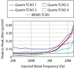
Figure 11 The PSNR of MEMS and quartz oscillators.
Airflow can cause changes in frequency and is another potential cause of performance degradation for outdoor small cells. Airflow can cause die temperature changes by changing the heat flow from the oscillator. Rapid, turbulent airflow can have an even more pronounced effect and, in extreme cases, can cause vibration effects. To show this, Figure 10 plots the ADEV of quartz TCXO and MEMS oscillators in the presence of airflow, using averaging times from 1 to 1,000 s. The MEMS oscillators have 2 to 38x better ADEV performance using averaging times between 1 and 100 s.
ADEV is a time domain measure of frequency stability. The main advantage of ADEV over standard deviation is that it converges for most noise types. Therefore, it is widely used for characterizing the frequency stability of oscillators. Good ADEV performance is particularly important for telecom-grade oscillators, and MEMS oscillators excel at ADEV performance.
In addition to external environmental stresses such as vibration, ambient temperature and airflow, internal system stresses are also present. Power supply noise can result from crosstalk with nearby data lines and switching regulators. To maintain system performance, it is important for the oscillator to maintain good phase noise and jitter performance in the presence of noise from the power supply. Power supply noise rejection (PSNR) is the ratio of jitter observed at the output, in picoseconds, divided by the amplitude of injected jitter on the supply pin, in millivolts. Normally, sinusoidal jitter is injected onto the supply voltage with a 50 mV amplitude. Figure 11 shows the peak-to-peak jitter of a MEMS oscillator compared to quartz oscillators from six different suppliers across the noise frequency range from 20 kHz to 40 MHz. The MEMS oscillator excels in PSNR. The low jitter is due to multiple on-chip low-dropout regulators, which isolate the critical components such as the VCO and MEMS oscillator.
Conclusion
MEMS oscillator technology has improved significantly during the past decade, including the key elements that comprise a high performance oscillator: the resonator, temperature compensation circuitry, PLL and on-chip voltage regulators. Building on the intrinsic advantages of shock and vibration resistance, state-of-the-art MEMS timing technology delivers best-in-class dynamic performance—resilience to system and environmental stresses. Compared to quartz oscillators, MEMS oscillators offer better frequency stability and aging, with no activity drops. They are up to 80 percent smaller and consume up to 90 percent lower power. MEMS oscillators are ideal for meeting the challenges of outdoor small cells. With additional investments in MEMS oscillator technology, refinements will continue to improve phase noise and frequency stability, making MEMS-based timing the solution of choice for the next several decades.
