
As the telecommunications industry rapidly migrates to the new 5G standard, we can expect unprecedented data speeds, low latency and high reliability communication. To support these advancements, millimeter wave frequency bands are being made available on a global scale for 5G base stations, backhauls, fronthauls and customer premises equipment. The wide contiguous bandwidths available at these newly assigned frequencies enable high data rates. Additionally, the associated short wavelengths allow physically compact electronic steerable (active) antennas to be deployed that offer spatial diversity, spectrum reuse and high antenna directivity (gain) to overcome the higher path loss encountered at millimeter wave frequencies.
The aerospace and defense industries have been manufacturing active antennas for decades, so the expertise needed for 5G solutions is not new. What is new, and what is now fueling the migration of these types of antennas to the commercial sector, are the advancements in high frequency silicon semiconductors, an IC technology that combines the required beam steering functions—vector (amplitude and phase) modulation and digital interfaces—with the traditional transmit/receive functions, all implemented in highly compact ICs that enable the fabrication of planar antennas, a requirement for cost-effective assembly. Only using silicon in these active antennas has driven the cost of these antennas down by orders of magnitude, making them suitable for high volume, mass deployment systems like 5G infrastructure.
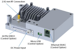
Figure 1 Control and signal interfaces on the rear panel of the AWMF-0129.
28 GHz ACTIVE ANTENNA FOR 5G
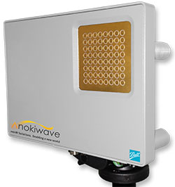
Anokiwave has developed beam steering ICs for active antennas for more than a decade and recently announced the AWMF-0129, the world’s first commercially available active antenna specifically designed for 5G infrastructure. Developed in collaboration with Ball Aerospace, the AWMF-0129 is a 64-element, single polarization 5G, rapid prototype phased array antenna designed to cover the 27.5 to 30 GHz frequency band. A planar antenna, it can be used either as a stand-alone component or combined and synchronized with other arrays to support hybrid beamforming and multiple-input-multiple-output (MIMO) functionality as part of a larger array.
To support 5G beam acquisition and various channel needs, the rapid prototype array supports and provides multiple beamwidths. A wide beam is available to support channel state information measurements, search modes and broadcast channels. Multiple progressively narrower beams can be used for beam acquisition. The narrowest beams allow for interference mitigation, optimizing the signal to noise ratio (SNR), maximizing equivalent isotropically radiated power (EIRP) and range extension. A two-dimensional scan volume of ±60° in both azimuth and elevation is supported. As this is a time-division duplex (TDD) system, the array operates in a half-duplex mode, enabling the same antenna to support both transmit and receive, with distinct transmit and receive beam settings if required.

Figure 2 Receive patterns with the array scanned from 0 to 60°.
The array also includes pre-stored beam states that, once loaded, can quickly be accessed in a beam acquisition protocol—an essential specification for any 5G radio physical interface. Each beam state is accessible in under 100 ns, meaning that the beam position of the entire array can be redirected in approximately 10 µs. The embedded digital controller receives a desired “look vector” (beam position coordinates in azimuth and elevation), calculates the required vector modulator settings at each element in the array and communicates with the silicon ICs to steer the beam within the allotted time slot. Completion of this entire operation within a sub-symbol interval (Ts = 13.33 µs) is a critical specification for the low latency requirements of proposed 5G radio systems.
The array specifies an EIRP of greater than +50 dBmi and a G/T—a measure of the noise sensitivity of the antenna—of greater than -8 dB/K at boresight. As green electronics becomes an increasingly high profile consideration, the overall energy efficiency of an array becomes more important. The two key figures of merit for an active antenna are the ratio of EIRP to total DC power dissipation (including all amplification and vector generation, digital controllers, signal telemetry and DC-DC conversion) and the G/T to effective aperture ratio, which is a measure of the noise performance of the array as a function of the effective aperture size. By careful architecture choice and minimizing front-end losses, the AWMF-0129 exceeds other competing approaches and technologies in these two key ratios.

Figure 3 Cross-polarization performance with the receive at boresight (a) and 40° θ (b).
Other features of the array include temperature compensated gain with full array temperature mapping, temperature sense telemetry and transmit output power measurement at each antenna element reported back to the host system as telemetry. Remote monitoring and control of each antenna with real-time operational data allows for greater flexibility. The active array can be controlled through several interface options, allowing the array to be synchronized with the timing and data requirements of the baseband modem or with other antennas. The interface options are either Ethernet, USB or high speed control low voltage differential signaling (LVDS).
The array measures 10.8 cm × 15.4 cm × 3.12 cm and weighs 500 g. It can be powered from either +12 or +18 V and consumes less than 25 W of DC power which includes the embedded controller for beam steering and array control. Figure 1 shows the rear panel of the array, illustrating the interface ports and array mounting connections.
The RF signal interface to the array is directly at the carrier frequency of the physical air interface. This provides an extra degree of flexibility, allowing use in a conventional test setup with external test equipment for channel characterization, evaluation of over-the-air modulated waveform statistics or integration with specific up- and down-conversion blocks for spectral emission evaluation. One of the key challenges with 5G radio development is understanding how frequency planning and signal characteristics will impact adjacent channel leakage ratio (ACLR) and spectral mask requirements for out-of-band spurious signals. Direct signal injection and reception at the RF carrier frequency allows the user to perform optimization and evaluation of frequency conversion proposals.
ARRAY PERFORMANCE
Figure 2 shows the far-field antenna pattern of the array in receive mode for scan angles from 0 to 60°. The patterns are well behaved with good sidelobe levels. Co-polarization and cross-polarization antenna patterns of the array in receive mode at both boresight and 40° θ scan are shown in Figure 3. Excellent cross-polarization is observed under both scan conditions, with measured isolation between the polarizations greater than 35 dB. The measured transmit EIRP of the AWMF-0129 achieves ≥50 dBmi at 1 dB compression (see Figure 4).
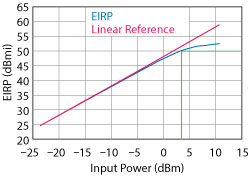
Figure 4 Measured transmit EIRP vs. input drive. The EIRP at 1 dB compression is ≥50 dBmi.
The AWMF-0129 is the world’s first commercially available electronically scanned active array available for fast prototyping and evaluation of millimeter wave environments for 5G applications. Based on highly integrated Si technology that includes embedded functions for remote telemetry and low latency fast beam steering of the entire array, the AWMF-0129 enables real-time active beam steering. By providing full flexibility in the choice of waveform stimulus and timing control, the array is an enabling technology to evaluate and develop multiple products.
Anokiwave Inc.
San Diego, Calif.
www.anokiwave.com