
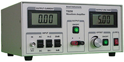
Many test and measurement applications require a driver amplifier that provides high voltage, high current or any combination. Typical benchtop signal sources — function generators, arbitrary waveform generators, signal generators and data acquisition systems — are unable to provide high voltage or current. The output of most benchtop generators is limited to about ±5 V into 50 Ω and 100 mA drive current. With a typical output resistance matched to 50 Ω, they can’t drive low resistance loads that draw high current. To address these needs, Accel Instruments developed the benchtop TS250 high voltage and high current waveform amplifier for general laboratory and test and measurement applications. The TS250 will provide an output voltage to 65 V and can drive more than 6 A. The TS250 is used to amplify function generators and other weak signal sources (see Figure 1), extending the function generator’s capabilities.
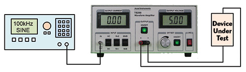
Figure 1Typical use of a waveform amplifier.
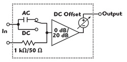
Figure 2 Functional block diagram of the TS250 waveform amplifier.
The TS250 power amplifier (see Figure 2) has a selectable voltage gain of 0 or 20 dB. 20 dB is normally used for applications that require high voltage, while 0 dB supports high current applications. The input impedance of the TS250 can be set to either 50 or 1 kΩ. The TS250 amplifier has very low output impedance (approximately 50 mΩ) to maintain signal integrity without distortion. A DC offset voltage can be added to the output signal, similar to the DC offset feature with most function generators. It can generate an AC signal on the DC voltage, which is useful for power supply ripple or ripple rejection tests.
WAVEFORM DISTORTION
Using a signal generator to drive a non-50 Ω load can attenuate and distort the desired waveform. When driving low resistance loads, the signal will be attenuated by the voltage division from the higher source impedance, as shown in Figure 3a. A square wave from a function generator may be distorted by capacitive or inductive loads (see Figures 3b and 3c). With a capacitive load, the source generator output resistance and load capacitance form a lowpass filter. With an inductive load, such as a relay or a magnetic coil, the generator output resistance and load form a highpass filter. Driving such loads from the TS250 waveform amplifier will not distort the waveform because of the TS250’s low source resistance and high current capacity.
Figure 3 Examples of waveform distortion when a 50 Ω function generator drives low resistance (a) capacitive (b) and inductive (c) loads.
APPLICATIONS
Piezoelectric transducers, electromechanical relays and power supplies are three applications that require higher voltage than is available from most function generators, i.e., from 10 to 65 V. Other applications present low impedance loads and require high current, such as generating a high magnetic field in a coil. Yet other cases — voltage transient and pulsed thermal transient testing — require both high current and high voltage. Some signal sources are weak and require amplification, such as data acquisition systems (DAQ). The output impedance of a DAQ is low, 1 Ω or so, with a limited current drive of 1 mA. DAQ analog outputs are designed to see a load of 1 kΩ or greater. In all of these applications, a waveform amplifier is needed.
A common product development test is power supply ripple injection and rejection, to identify amplifier spurs or phase and amplitude noise caused by noise from the power supply. This requires generating an AC ripple voltage on top of the DC supply voltage and sweeping the ripple frequency from near DC to 1 MHz. The AC ripple is usually a sine wave, although it can be any waveform, such as a square or triangle wave or random noise. The test is particularly difficult when the device being tested draws high DC current. Figure 4 shows how the TS250 waveform amplifier is used for ripple injection testing. Using a network analyzer in place of the function generator and oscilloscope or spectrum analyzer enables measurement of the power supply ripple rejection ratio (PSRR).
Figure 4 Test setup for power supply ripple rejection.
Helmholtz coils are commonly used to generate uniform magnetic fields; however, producing high frequency and high magnetic fields is challenging, requiring high current drive. Using a series capacitor to tune the Helmholtz coils to resonance cancels the coils’ reactance, reducing the coils’ impedance from 10 kΩ to less than 1 Ω, or just the parasitic resistance of the coils. The TS250 amplifier can drive up to 6 A through the coils to produce high magnetic fields at high frequencies.
Accel Instruments
Irvine, Calif.
www.accelinstruments.com