
Of high importance among the many considerations that need to be taken into account when designing new products in an evolving market is the intended user. Improvements in performance alone will not impress and significant attention must be paid to the practical issues, including convenience and the time consumed in set up and operation.
In the world of satellite communications, the traditional equipment supplied for facilitating off-line tests and providing continuous quality monitoring in a ground station installation is the Loop Test Translator (LTT). Input to the LTT is provided by tapping into a transmission path and translating the sampled signal back to the receive path but, with today’s compact mobile systems, often capable of high data rates, in-system connectivity may not be available and another test method has to be found.
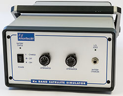
If a hard-wired solution is not viable, an alternative is to make tests using RF and, in this case, the very RF signal with which the mobile station communicates with the satellite is utilized. This is how AtlanTecRF’s newly introduced LSS Satellite Simulators operate. Figure 1 shows the front of the unit complete with antennas.
So, how does it work? Imagine the Ka-Band system buried deep within the airframe of a commercial airliner, military transport or executive jet whose only visible presence is the antenna blister on top of the fuselage. The system provides internet and data services to crew and passengers at bandwidths normally only achievable at home or in the office. To test the transmission path, the LSS is placed on the platform of a ‘cherry picker’ — a standard piece of aircraft maintenance equipment. So, while the aircraft is in its hangar, the live test can be carried out.
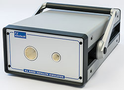
Figure 1 LSS Satellite Simulator with antennas on the front.
The LSS is powered by an internal rechargeable battery, with 24 hour duration, thereby ensuring its total autonomy in the loopback test function, where it becomes a simulated satellite. Reception from the system under test (SuT) and transmission back to it is achieved by a pair of horn antennas. The receiving antenna terminates in WR42 for the SuT 30 GHz uplink band and the transmitting antenna terminates in WR28 for the SuT 20 GHz downlink band.
In each case, the transmissions between LSS and the SuT can take place in both left hand and right hand circular polarizations simultaneously, thereby further establishing the similarity between the test condition and an actual operating situation, live on the satellite.
While it would be possible to control the instrument remotely during tests, avoidance of Wi-Fi or other unnecessary radiations is achieved using purely manual controls (see Figure 2) which, once initially set for the range involved, should not require further adjustment.
For each polarization there is a signal path attenuator which can be set and locked and, while the translation paths within the instrument remain independent, each is served by a common local oscillator (LO) at either 9.8 GHz or 10.3 GHz, depending on the actual Ka-Band frequencies of the SuT.
The style of the instrument case used for the LSS is such that the carry handle can be folded back and used to point the antennas at the SuT on the aircraft but the individual horn designs are of a type where a degree of misalignment in both the vertical and horizontal planes, up to 10 degrees, can be tolerated without loss of performance in the loop test. The size of the LSS is just 260 mm × 150 mm × 420 mm (10.3" × 5.9" × 16.5") making it very easy to maneuver into position and align with the system being tested.
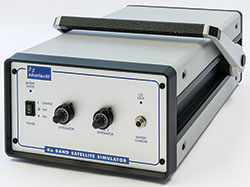
Figure 2 Once the manual controls on the back of the unit are initially set for the range involved, they should not require further adjustment.
Frequency stability is provided by a high quality internal OCXO, again for autonomy, and LO phase noise, while not needing to be to transmission standards for the tests, is nonetheless good at -100 dBc/Hz at 10 kHz offset.
The attenuator in each polarization path is continually variable over a 30 dB range and can be set to mimic typical atmospheric conditions even though the tests would normally take place in a sheltered environment and over a SuT to LSS distance of around 30 m. Variants with amplification are also offered where the test range distance is considerably greater, in which case the nominal -35 dB conversion gain of the LSS can be increased up to +30 dB with close to 1 W of available output power in the downlink band.
Although just one typical application for the satellite simulator is described here, namely airborne systems, the same principle and the same product can be employed for vehicular, railway and marine systems as well as portable flyaway and manpack products.
Equally, there is a Ku-Band version, for a similar range of applications, which will loop back the common uplink frequencies to the multiple downlink frequencies, albeit with larger antennas in a slightly increased instrument size.
Throughout the product development from concept through to delivered hardware, ease of set up and application has been a dominant consideration, thereby saving considerable elapsed test time with greater speed into service for the system under test. Where airline service is concerned, this is a very significant factor.
AtlanTecRF
Braintree, Essex, UK
www.atlantecrf.com