
This antenna system provides omnidirectional coverage of telemetry, tracking and command (TT&C) communication links for a student satellite. The compact, lightweight antenna is designed for dual circular polarization in S-Band (2.0 to 2.3 GHz), covering both the transmit and receive TT&C frequency bands. Two cross polarized antennas mounted on opposite sides of a nano or micro satellite assure 100 percent coverage with acceptable gain at both transmit and receive frequencies.
Conventional methods of mounting two antennas of the same polarization on opposite sides of a satellite cannot provide full omnidirectional coverage because considerable interference in the overlapping coverage areas creates deep radiation pattern nulls. This typically provides about 85 percent coverage with considerable zones having gain as low as -10 dBi. 1 A configuration for obtaining nearly full coverage with acceptable null depths is discussed in this article. Two antennas with hemispherical coverage of opposite polarization, left hand circular (LHC) and right hand circular (RHC), when mounted on opposite sides of a satellite, provide omnidirectional coverage in two polarizations.
Figure 1 Basic configuration of the omnidirectional antenna system.
Figure 2 Omnidirectional antenna system with dual polarized antennas.
Figure 3 Isotropic (a) and side (b) views of the antenna configuration.
Variants of a helical antenna are conventionally used onboard low earth orbit (LEO) satellites for obtaining circular polarization with wide bandwidth. The size of these antennas, however, restricts their use on-board micro/nano satellites. Microstrip patch antennas, by virtue of their low profile, light weight and small size are preferred for satellite applications, but conventional microstrip antennas2 cannot support the total TT&C frequency band of a satellite and also provide good axial ratio. To overcome this problem, separate antennas for receive and transmit are considered. Figure 1 shows a typical antenna system for achieving omnidirectional coverage with acceptable gain; this configuration uses four antennas.

Antenna cross polarization isolation through the use of receive and transmit antennas of opposite polarization also reduces bandpass filter isolation requirements. The ground station will have the provision to receive signals in dual polarization and apply diversity combining for optimum performance. The transmit signal can be sent in either polarization based on the received signal strength. Alternatively, transmission in linear polarization will simplify ground station transmission, albeit with 3 dB degradation in the uplink; it is straightforward to transmit 3 dB higher power from the ground station to overcome polarization loss.
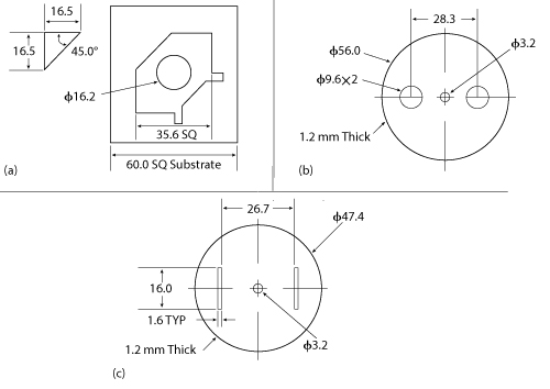
Figure 4 Dimensions (mm) of the corner truncated patch on TLC-30 substrate (a) circular parasitic patch 1 (b) circular parasitic patch 2 (c).
Figure 5 Simulated return loss at the LHCP and RHCP ports.
Dual Polarized Wide Bandwidth Antenna
A wideband antenna with dual polarization capability can reduce the number of antennas (see Figure 2). To achieve this, a dual circularly polarized microstrip antenna coupled with two circular shaped parasitic patches is designed and developed. Broad bandwidth, compact size, light weight, good port-to-port isolation and dual circular polarization with good axial ratio are the main features of the design. The antenna consists of two electromagnetically coupled circular parasite patches aligned over a microstrip radiating patch fabricated on a low loss substrate.3 The three patches are separated by air layers (see Figure 3).
The basic microstrip patch is printed on a 4.75 mm thick dielectric substrate having an εr of 3.0. The antenna is fed by two coaxial probes (P1 and P2), placed orthogonally to obtain LHC and RHC polarizations. To enhance the bandwidth, two circular passive patches with a pair of holes and slits are stacked over the substrate with spacing optimized for performance. Holes are made on the immediate circular parasitic patch, and slits are cut on the second parasitic circular patch. These patches are aligned over the diagonal of the basic microstrip patch. The antenna dimensions are shown in Figure 4. Opposite corners of the square patch are truncated, as illustrated in Figure 4a, in order to excite two orthogonal modes. Pairs of holes and slits are located diagonally on the circular parasitic patches 1 and 2, respectively (see Figure 4b and 4c), to achieve a good axial ratio and good impedance matching over the required frequency band of operation. The dimensions and positions of the holes and slots are adjusted through a number of iterations to broaden the beamwidth and optimize the axial ratio. A 1 mm spacing between the truncated radiating patch and circular parasite patch 1 and an 8 mm spacing between circular parasite patch 1 and circular parasite patch 2 are found to provide the required performance.
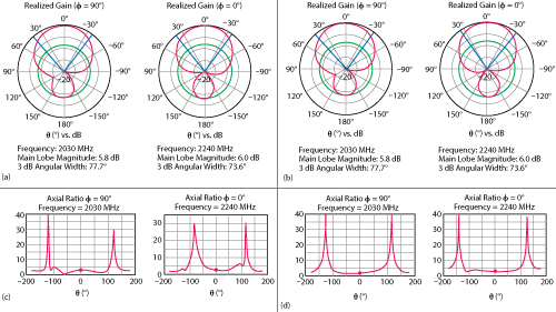
Figure 6 Simulated radiation patterns at 2230 and 2240 MHz of LHCP port 1 (a) and RHCP port 2 (b). Simulated axial ratio at 2230 and 2240 MHz of LHCP port 1 (c) and RHCP port 2 (d).
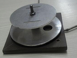
Figure 7 Dual circularly polarized antenna prototype.
Simulation and optimization were performed using the transient solver in CST Microwave Studio®. Simulated return loss for both LHCP and RHCP ports over the frequency band of interest are plotted in Figure 5. Radiation patterns and axial ratio for both ports at 2030 and 2240 MHz are shown in Figure 6.
Test Results
Figure 7 is a photograph of the prototype dual circularly polarized antenna. Radiation patterns at the center frequency (2130 MHz) for the LHC (Port 1) and RHC (Port 2) polarizations are shown in Figure 8. An axial ratio of less than 3 dB is achieved over the full frequency band. Port-to-port isolation measures 14 dB at 2030 MHz, improving to 19 dB at 2240 MHz. VSWR is less than 1.4:1 across the band.
Two antennas have been mounted on opposite sides of a student nano satellite (PISat) being developed at the PES Institute of Technology in Bangalore, India. The satellite is 254 × 226 × 180 mm in size. The receive and transmit ports of the antennas are connected as shown in Figure 2. Figure 9 shows the combined radiation patterns measured in an anechoic chamber at the receive (2030 MHz) and transmit (2240 MHz) frequencies. The total variation in the measured combined radiation pattern is 10 dB, with a minimum antenna system gain of -7 dBi and a peak gain of about +3 dBi. The patterns show that 100 percent coverage can be obtained with a minimum gain of -7 dBi.
Conclusion
A simple configuration for achieving omnidirectional coverage on-board a satellite, using dual circularly polarized microstrip patch antennas, has been presented. A wide bandwidth, dual circularly polarized truncated corner microstrip antenna coupled with two parasitic patches was designed, simulated and optimized. Diagonally embedded holes and slots on the parasitic patches significantly improve cross polarization bandwidth. The antennas were mounted on a nano satellite and tested in an anechoic chamber. Complete coverage was obtained with a minimum of -7 dBi antenna gain. The model may be easily scaled to any other frequency band.
Figure 8 Measured RHC and LHC radiation patterns at 2130 MHz.
Figure 9 Measured combined radiation patterns at 2030 MHz and 2240 MHz.
Acknowledgments
The authors wish to acknowledge the support extended by Kavveri Telecom Products Ltd., Bangalore, for simulation, fabrication and testing and would like to thank Dr. TS Chandar, HOD, Dept. of ECE; Dr. V.K. Agrawal, Director, CORI; and Dr. K.N.B. Murhty, Vice Chancellor, PES University for their encouragement.
References
- S. Pal, V.K. Lakshmeesha, L. Nicholas andV. Mahadevan, “Omni Directional Antenna Systems for Indian Satellites,” Proceedings of the 15th International Symposium on Space Technology and Science, Vol. 1, May 1986, pp. 993–998.
- C.A. Balanis, “Antenna Theory Analysis and Design,” Wiley, 2005.
- C.L. Li, H.H. Wang, H.J. Linand X.W. Shi, “Analysis and Design of Broadband Microstrip Patch Antenna With a Pair of Double Cross-Shaped Slots,” International Conference on Microwave and Millimeter Wave Technology, May 2010, pp. 18–21.