A diplexer circuit, as shown in Figure 1, is a very practical circuit for dividing the frequency spectrum into essentially two non-overlapping parts. Crossover attenuation (Ao) as a design parameter has been unavailable in the past, thus limiting the designer’s options. This is no longer a constraint with Amplitech’s new design. The designer now has the option to increase channel to channel isolation as required by using the variability of the crossover attenuation.

Figure 1 Diplexer circuit.
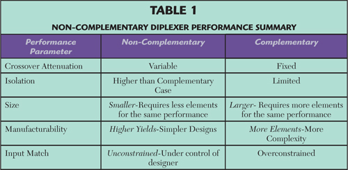
Complementary diplexers exhibit a near perfect input match across the entire band of coverage. The cost of this is an inherent restriction in the crossover attenuation to 3 dB (i.e., a half power split). For many applications, this level of crossover isolation is too small. Such design limitations can be circumvented only by giving up the match at the input and going to a non-complementary design.1 This allows controlled interaction between the input impedances to each diplexer channel. A greater level of selectivity is also achieved for a given number of elements per ladder. This permits smaller size and lower loss for a given level of rejection.
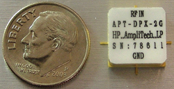
Figure 2 Diplexer construction employing surface mount packaging.
For a given rate of cutoff in the complementary class, each channel with v elements per ladder, experiences a cutoff rate of “6v dB per octave,” while in the non-complementary class described herein, each channel with v elements per ladder, experiences a cutoff rate of “2 × 6v dB per octave.” This is due to the contributory influence of the neighboring channel resulting in designs which are able to fit in smaller volumes for the same selectivity, because fewer elements per channel are required when both channels contribute to the response. This provides more “bang for the real estate buck.”
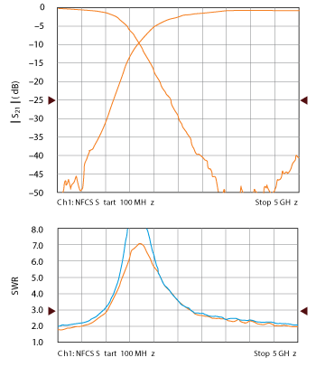
Figure 3 Surface mount diplexer measured data.
One may control the width of the transition region that exists between bands (i.e., where S11 is no longer to be matched) to any desired degree through the choice of ν with great effect.1 Thus, the effect of the mismatch is limited to an inconsequential band of frequencies. Other approaches that attempt to increase selectivity in this region often include topologies which are more complicated, since they are suboptimal and may involve the use of finite transmission zeros to improve selectivity where they might otherwise be avoided. Amplitech’s topology avoids the use of finite transmission zeros altogether. Designs are built with a minimum of complications providing more “bang for the manufacturability buck.”
Circuit Construction and Data
The present goal for this design example was to complete the circuit construction while employing a surface mount (SMT) package and taking advantage of all of the benefits associated with such packaging. This includes size, ease of manufacturability and cost. The result of this effort is shown in Figure 2.
The test data is shown in Figure 3, where the attenuation for each channel is shown overlaid in the graph on the top and the SWR results are shown on the bottom of the figure for each of the three ports. The measured data was in good agreement with the initial design parameters. Good rejection was achieved with both good match and isolation.
A test fixture was developed as part of this effort. When the SMT package is loaded into this fixture, the assembly can be tested using a typical network analyzer test set-up employing SMA (or other similar types) connections. Once tested, the SMT package may be removed from the test fixture. With connection tabs now exposed, the SMT diplexer may then be integrated into a higher level of assembly where it might be used in its intended application. The SMT diplexer may remain in the test fixture for continued use in system applications where the SMA connections are preferred to the tab connections. The fixture is shown in Figure 4. A trade off comparison for each diplexer type is given in Table 1.
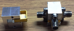
Figure 4 New test fixture for the SMT diplexer.
Applications
The construction of Amplitech’s new type of variable crossover, ladder realizable diplexer in an SMT package, has been practically demonstrated. The features of this design class are summarized in Table 1. The applications for this circuit include cell phone (separating GPS from other signals); mixer design enhancement; multi-channel communication systems; as well as SATCOM and EW systems. This circuit facilitates higher levels of system integration since passive circuits such as diplexers are often “tall poles” in the system size requirements. Future efforts will explore the use of even smaller packaging.
Reference
- D.C. Youla, S.U. Pillai and F. Winter, “Theory and Design of Maximally Flat Low-Pass High-Pass Reactance Ladder Diplexers,” IEEE Transactions Circuits and Systems, Vol. 39, No. 5, 1992, pp. 337-350.
Amplitech Inc.
Bohemia, N.Y.
(631) 521-7831![]() (631) 521-7831
(631) 521-7831
www.amplitechinc.com