

Figure 1 Rendition of a smallsat showing a deployable panel antenna concept.
The past decade has witnessed a massive growth in interest in satellites that are smaller, cheaper and quicker to deploy than larger space-borne assets. One of the major challenges associated with these platforms, however, has been the limited communications bandwidth available to and from them. While the communications industry has done a stellar job in improving available radios and amplifier equipment, antenna systems for satellite platforms continue to be challenged with meeting size, weight and power requirements while still providing the flexibility demanded by the mission set. In this article a new antenna design platform will be introduced, and its effects on space-communications will be discussed.
Small satellites, so-called ‘smallsats,’ have captured the imaginations of hobbyists, entrepreneurs and the wider aerospace industry (see Figure 1). The interest in these platforms is being driven by both cost and technical considerations. Smallsats can be deployed quickly and cost-effectively, allowing new technologies to be adopted rapidly in an industry that is famous for risk aversion. While the cost of launching a satellite is being driven down by entrepreneurial companies such as SpaceX, the availability of powerful sensors and communications equipment is being driven lower by volume applications on Earth. The average cell phone is now capable of doing much of what a powerful satellite was once required to do.
There is no cellular network available for satellites, though. Information collected by a satellite must be broadcast from the satellite to an earth-terminal in order to be accessed; and this is one of the most significant challenges facing the smallsat industry. A typical cube-sat will be outfitted with a UHF communications payload, which, when paired with a large tracking earth terminal, is capable of a few kbps. This shortage on connectivity has resulted in a misperception within the industry that smallsats are interesting, but only to amateurs interested in hearing a satellite go ‘ping’ from orbit. This is unfortunate because a spacecraft travelling in LEO and operating in the Ka-Band would be capable of gigabit connections, significantly higher than the connectivity available to even very large communications satellites operating from the GEO arch.
The bottleneck to providing gigabit levels of throughput to LEO smallsats is the antenna. The use of communications at X-Band and above generally requires some directivity from the antenna (typically 30 dB+ of gain). This gain is necessary to achieve the desired throughput and avoid interference with others in the same band. Gain levels of 30 dBi+ are easy to achieve using a reflector based antenna, but in a LEO orbit the antenna must also be capable of tracking. On a smallsat platform this currently must be accomplished either using mechanically gimbaled systems or by repointing of the satellite itself with its inertial stabilization system. The former (gimbaled) approach requires a set of motors that are relatively heavy and power consumptive. In fact, the motion of the antenna itself will impart momentum to the satellite and move the satellite itself.
The alternative is to use the momentum wheel of the satellite itself to point the satellite and dish simultaneously. The challenge with this approach is that the orientation of the satellite is now intimately connected to the communications direction. In earth observation applications this leads to large latencies in data-backhaul because the satellite sensors must be pointed on a first-pass, and then backhaul must be done on a second pass over a region. Given that a typical LEO orbit is in the range of a few hours, this approach makes real-time or near real-time sensing impossible from these platforms. In communications architecture the situation is worse. The relative positions of the Earth-station and the backhaul source (either teleport or inter-satellite link) of a moving satellite will move with respect to one another, and cannot be managed through the orientation of the satellite alone.
To address these communications challenges, a reconfigurable high-gain antenna with no moving parts and a small size, weight and power footprint is required. Through the dual use of metamaterial and liquid-crystal technologies, companies like Kymeta are spearheading the effort to create such antennas.
Technology
The antenna designs described here operate on the principle of reconfigurable holography. In such an architecture there is a feed which remains fixed throughout the operation of a device. The design challenge is to create a medium for scattering this feed-wave in a controllable way such that a requisite phase distribution can be developed over the surface of the antenna. In the design described here, this scattering is mediated through the use of a multitude of reconfigurable scattering sites aggregated together on a highly sub-wavelength scale. The use of such aggregations of scattering sites results in a device governed by the design paradigm known commonly as metamaterials.
Figure 2 The simulated electric field magnitude above a resonant cell is shown in two states.
Unlike phased-array antennas, devices constructed in this manner require no active components in the RF chain. The reconfigurableability of the antenna is built in to the metamaterial elements, and in this case liquid crystal is used. Nonetheless, the theory of operations is accessible through the well-known array-factor equations which govern the beam performance of a phased-array antenna.
In equation 1, the controlled element is the phase, γm, with which each antenna element is fed. In equation 2, the phase is not dynamically controlled, but a travelling wave feed is used such that every element is fed with a variable phase (which is not time-dependent). In equation 2, the wave is assumed to be traveling along the x-axis. The phase of each element is determined by the position along that axis. The control mechanism is the amplitude with which each element scatters energy from the feed wave and into the far-field. This process will work to form antenna beams that can be scanned to any angle, subject only to the physical limitations of the subtended angle of the aperture with the direction of scan.
The fact that the antenna feed is integrated into the radiating aperture reduces the size, weight and complexity of the feed manifold. In practice the entire antenna can be built within a thickness of less than 1 cm; with associated weight savings.
Figure 3 Beam performance for a small aperture prototype antenna operating at 30 GHz.
The amplitude control can be implemented in many ways, but in our case we use a tunable dielectric – liquid crystal – to dynamically adjust the frequency with which each of our metamaterial elements resonates. When the frequency of operation is close to the resonance frequency of an element it scatters strongly; conversely, when the resonance frequency is tuned away from the frequency of operation the element scatters very weakly. This is shown explicitly with resonant curves in Figure 2. Interestingly, in between the two resonant points a phase hologram is formed due to the 180 degree phase offset of the emitted signal associated with traversing the resonance.
The resonant elements work together through constructive interference to form an antenna pattern. One example antenna pattern from a prototype operating at 30 GHz is shown in Figure 3. Without a bias voltage applied the resonance is at a higher frequency (green line in Figure 2). When a bias voltage is applied the effective permittivity of the liquid crystal which loads the capacitive region of the resonator is increased and the resonant frequency is lowered.
Element Tuning and Liquid Crystal
The resonance frequency of the individual elements can be modulated by changing the effective capacitance in the resonator. The case of an in-plane capacitance in a resonator is shown in Figure 4. This particular design is a complementary-ELC, or CELC, resonator.1 In this case, the resonator is excited through an iris and has a well-defined resonant frequency determined by the inductance through the cell and the capacitance between the central region and the ground plane. In the center of the resonator, shown in Figure 3, there is an inductive region. Along the edges of the resonator there is a capacitive region between the resonator itself and the ground plane. Liquid crystal is added to this region as a tunable dielectric loading material. A bias line is threaded through the null region of the resonator so that a voltage difference between the CELC resonator and the ground plane may be applied.
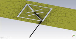
Figure 4 An example CELC resonator.
Liquid crystal can be introduced to the capacitive region by simple means as it is naturally exposed. The liquid crystal used is in this case is a nematic phase material in which the dielectric constant is anisotropic and best described as a tensor. Liquid crystal molecules are long and thin. The long axis of the LC molecules has a naturally higher polarizability than the two shorter axes. The effective dielectric constant along these axes are ε||and ε⊥ respectively.
The local orientation of the LC molecules, called the director, is a free-variable which can be manipulated by the application of an electric field. For the purposes of calculation, the orientation of the LC molecules can be found from FEM analysis based on well-known free-energy contributions in equation 3. Once the director axis is calculated the permittivity tensor can be found in the volume using the orientation of the director axis denoted by θ and θ in equation 4. The capacitance of the unit cell can then be found by calculating the stored energy in the gap region (equations 5 and 6).
In the case of metamaterial unit cells based on the complimentary ELC resonator structure, the orientation of the liquid crystal itself can be modulated through the application of a bias voltage to the central island of a unit cell. This bias is entirely capacitive, resulting in no continuous current draw and minimal total power requirements. In practice, less than 2 W of power are required for even large antenna panels. In principal, it is possible the power draw could be limited to several milliwatts.
One of the particularly intriguing aspects of liquid crystal for space applications is that LC is naturally radiation hardened. Studies have shown no observable systematic effects from even very high levels of radiation from Cobalt 60 and neutron sources.1 Regardless of architecture, this makes the use of LC attractive for these applications.
The use of liquid crystal in space applications is not without its challenges. One example is the thermal operating range. Decades of research into materials for the display industry have yielded materials which can operate over very large temperature variations. A typical material used in the display industry will have a temperature range in which it remains in the nematic phase from -25° to 160°C. If the desired operational temperature is colder than the nematic range, some heat will need to be provided to ensure that the LC remains in its nematic phase.
System Analysis
While it is beyond the scope of this article to provide a full satellite systems analysis, it is worthwhile to briefly emphasize the improved link performance over similarly equipped GEO spacecraft and LEO spacecraft utilizing semi-isotropic radiators. Table 1 emphasizes the impact of bringing satellites from 35,000 km away into a LEO orbit. The decrease in distance provides a significant improvement in signal strength when compared to satellites in geosynchronous orbit. If the same assumptions are made for antenna size and power level, a satellite in LEO orbit can provide 1,000x the data rate. If scanning is not available, omni or near-omni directional antennas are needed to operate effectively from a LEO orbit. This is commonly done, for instance, at S-Band. In this case the link supports a similar data-rate to GEO.
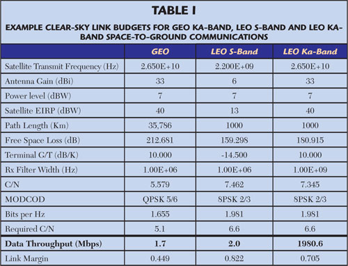
A large, high-gain antenna on the earth station can alleviate some of the challenges at S-Band and improve the link performance (note: a quasi-omnidirectional S-Band earth station antenna was also assumed in the analysis). However, even with this infrastructure in place, there is a limited amount of bandwidth available at S-Band and it is broken into several bands. Even if the link performance were identical, the 1.5 GHz of bandwidth available for space-to-earth applications between 25.5 and 27 GHz gives the higher frequency solution a clear advantage.
For use cases such as data backhaul from Earth-observation satellites, the impact is clear. Real-time tracking over a large scan range allows for coverage without the latency of a second-pass; while multi-gigabit connectivity is possible because of the favorable link margin and large bandwidth available at Ka-Band.
The use case for a typical satellite communication architecture is more subtle. While the link margin is strong, the coverage area will be small due to the high gain aperture onboard the satellite and the distance of the orbit. At 1,000 km, for instance, a 2° beam will cover approximately a 30 km diameter region. This small coverage region potentially makes wide area coverage models cost-prohibitive to deploy using currently available launch methods. However, in circumstances in which high data-rates are needed in concentrated areas such a constellation could be enabling. As deployment costs to LEO orbit drop, additional capacity can be added or a multi spot-size architecture could be considered. As more capacity is added to the system, the deficiency of a small spot size becomes a significant advantage due to the frequency reuse it affords.
Conclusion
The smallsat industry has a bright future that is being driven by reduced cost of access to space, powerful sensors and increasing global demand for information and communication. However, connectivity to these platforms remains a significant challenge. The platform antenna technology described in this article shows promise for overcoming these challenges by providing flexible high-frequency connectivity with an appropriate size, weight and power footprint.
References
- D. Schurig, J.J. Mock, and D.R. Smith, “Electric-Field-Coupled Resonators for Negative Permittivity Metamaterials,” Applied Physics Letters, Vol. 88, 041109, 2006.
- C. Uber, M. Tremer, S. Lane, E. Gallagher, S. Collins and M. Benoie, “Testing of Liquid Crystal Optical Phase Shifters for Space Survivability,” MILCOM, 2008.