
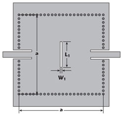
Figure 1 Configuration of the dual-mode square SIW cavity with one slot line.
This article describes a dual-mode, dual-band substrate integrated waveguide (SIW) filter. The dual-mode resonator is constructed with a slot line on the top metal layer of the SIW cavity. The two-pole dual-passband Chebyshev frequency response is achieved by cascading two resonators, with the center frequency of the second passband independently controlled by the geometric parameters of the slot line. Fabricated using standard printed circuit board technology, the filter is compact, has a high degree of design freedom and is low cost. Its measured S-parameters agree closely with simulation.
To meet various wireless communication requirements, dual-band filters have been proposed as key components in dual-band microwave and millimeter-wave communication systems. Substrate integrated waveguide, which is synthesized on a planar substrate with linear periodic arrays of metallic vias or metallic slots using standard printed circuit board (PCB) or other planar circuit processes, provides an attractive platform for higher Q value, higher power handing and more highly integrated waveguide filters.1,2
A number of topologies based on SIW resonators have been studied and developed to realize high Q with a dual-passband response. They can usually be reduced to two general approaches. The first uses several inverter coupled resonators to realize dual-band operation.3The dual passbands, however, are too close to each other, and many SIW cavities result in a large circuit size. The second utilizes standard low temperature co-fired ceramic (LTCC) technology to implement multilayered quadruple-folded SIW dual-passband filters.4,5 The bandwidths of both passbands are independently adjustable, but this method is often too costly. For circuit miniaturization, some dual-mode single passband filters have been designed in SIW technology,6-8however, these dual-mode cavities cannot be used to design dual passband filters.
This article describes the design of a dual-mode SIW resonator that is perturbed by a slot line on the top metal layer of the SIW cavity to achieve a two-pole dual passband response, with the center frequency of the second passband controlled independently by the dimensions of the slot line. The filter circuit is compact in overall size in comparison with traditional single-mode SIW filters.
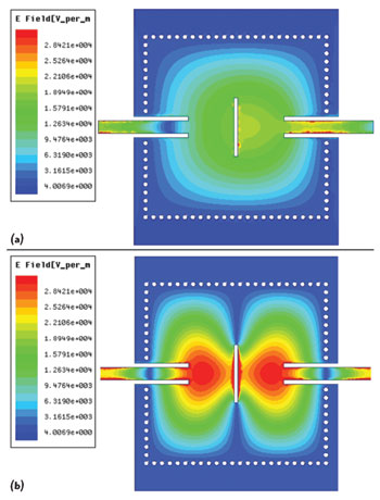
Figure 2 Electric field distributions of the TE101 mode (a) and TE102 mode (b).
ANALYSIS OF THE DUAL-MODE CAVITY
The configuration of the dual-mode square SIW cavity with a pair of coplanar waveguide (CPW) I/O feed line is shown in Figure 1. The cavity size is determined by the corresponding resonant frequency. The resonant frequency of the resonant modes (TEm0n) can be calculated using the following equation:9
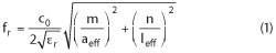
where aeffand leffare the effective width and length of the dual-mode SIW cavity, respectively, m and n the indices of the modes, εrthe permittivity of the substrate material, and c0the velocity of light in free space.
For a square cavity, the TE102and TE201 modes resonate at the same frequency if there is no disturbance. With the addition of a slot line, the TE201 is suppressed by the electromagnetic field perturbation caused by the slot, while the resonant frequency of the TE102mode can be controlled by the length of the slot (L1). The electric field distributions of the two modes (TE101and TE102) at L1= 7.5 mm, W1=0.5 mm are plotted in Figure 2 (a) and (b), respectively. It is apparent that they are concentrated around the center of the SIW cavity and the slot line.
Figure 3 shows simulated results of the dual-mode SIW cavity with variation of L1. The resonant frequency of the TE102mode trends lower with the increasing length of L1, while the resonant frequency of the TE101mode remains unchanged. The highest resonant frequency of the TE102 mode cannot exceed the first spurious mode of the single-mode cavity (L1=0 mm).
DUAL-PASSBAND FILTER DESIGN
Figure 4 shows the filter’s physical structure. The circuit consists of two identical dual-mode cavities. Magnetic coupling between two cavities is realized by an iris in the common post wall. The two resonators are excited by a pair of 50 Ω coplanar waveguide (CPW) I/O feed lines. The TE101- and TE102-modes of the dual-mode resonators are excited in order to realize the first and the second passbands. Figure 5 shows the coupling topology, where “1” and “2” are the first and second cavities, respectively.
Initial lengths and widths of the cavities are determined by setting the center frequency of the first passbands to their design values using Equation 1. The dimensions of the slot line are determined based on Figure 3. To determine the internal coupling coefficients, the two SIW cavity resonators are simulated using a commercial full-wave electromagnetic simulator (HFSS). The coupling coefficient is extracted using the following relation:10
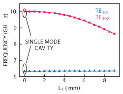
Figure 3 Frequencies of the TE101 and TE102 modes versus slot line length.
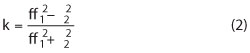
where f1and f2are the first and the second cavity resonant frequencies of the TE101- or TE102-mode, respectively, and k represents the coupling coefficient between the two SIW cavity resonators, which have been analyzed by Chen and Wu.11
In order to determine the external quality factor, numerical analysis with HFSS is carried out with the dual-mode SIW cavity bandpass resonator connected to two 50 Ω coplanar waveguide (CPW) I/O feed lines. Coupling is controlled by changing the dimensions of the feed lines (L3and W2). The external quality factor Qeis calculated with the equation:
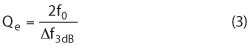
where f0is the frequency at which S21reaches its maximum value and Δf3dBis the bandwidth for which the attenuation of S21is 3 dB from its maximum value.
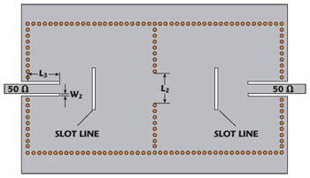
Figure 4 Two-pole dual-passband SIW filter structure.
The specified center frequencies of the first and second passband are 6.2 and 8.8 GHz, and the specified bandwidths of two bands are 300 and 600 MHz with return losses of 20 dB and 15 dB, respectively. Much work has been done on filter synthesis using coupling matrices.12The [N+2] ideal coupling matrix (M) of the first passband and second passband is derived using Equations 4 and 5. The coupling coefficients and external Qecan be computed from M using Equation 6.
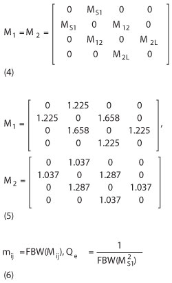
The coupling coefficients and Qeof two passbands are m12=m21=0.0802, Qe=13.78 for the first passband, and m12=m21=0.8774, Qe=13.64 for the second passband.
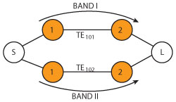
Figure 5 Filter coupling topology.
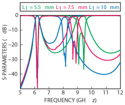
Figure 6 Simulated frequency response with L1 variation.
Based on Equations 1 through 6, the initial dimensions of the entire filter are estimated using HFSS. A fine tuning procedure is then employed for optimizing the design. Figure 6 shows the full-wave simulation dual-passband responses with different slot line lengths. The center frequency of the second passband is adjusted independently by changing the length of L1, with no apparent effect on the first passband.
Simulation and Measurement
The dual-passband SIW filter with a two-pole Chebyshev response is fabricated on 0.0508 mm thick Rogers RT/Duroid 5880 using a standard PCB process. The linear arrays of metalized via-holes all have diameters of 0.6 mm with a center-to-center pitch of 1 mm. Through simulation and optimization using HFSS, other dimensions are determined to be a=23 mm, L1=7.5 mm, L2=6.96 mm, L3=5.9 mm, W1=0.5 mm and W2=0.55 mm. Figure 7 is a photograph of the fabricated dual-mode, dual-passband filter, having overall dimensions of 23 × 46 mm.
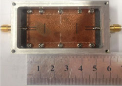
Figure 7 Fabricated dual-mode dual-passband SIW filter.
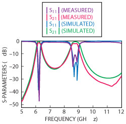
Figure 8 Simulated and measured frequency responses.
An Agilent 8757D network analyzer was used for measurements. Figure 8 compares simulated and measured results. The measured minimum passband insertion losses are 1.1 and 1.6 dB, respectively. Measured 3 dB fractional bandwidths are about 4.6 and 6.3 percent, respectively, for the first and second passbands, and the return losses of the two passbands are better than 12 dB. Slight differences between simulated and measured results may be due to fabrication tolerances and the added insertion loss of SMA connectors.
Conclusion
Two single-cavity, dual mode SIW resonators with slot lines on their top metal layers provide a dual-passband Chebyshev frequency response when cascaded. The center frequency of the second passband can be independently controlled by adjusting the slot line dimensions. The filter is small, has a high degree of design flexibility and is low cost. Agreement between simulated and measured results provides design verification.
Acknowledgment
This work is supported by National Natural Science Foundation of China (Grant No. 61201004) and the Fundamental Research Funds for the Central Universities (ZYGX2011J011)
References
- K. Wu, D. Deslandes and Y. Cassivi, “The Substrate Integrated Circuits-A New Concept for High-Frequency Electronics and Optoeletronics,” Proceedings of the 6th International Conference on Telecommunication in Modern Satellite, Cable and Broadcasting Service, Vol. 1, October 2003, pp. P-III-P-X.
- D. Deslandes and K. Wu, “Integrated Microstrip and Rectangular Waveguide in Planar Form,” IEEE Microwave and Wireless Components Letters, Vol. 11, No. 2, February 2001, pp. 68-70.
- X.P. Chen, K. Wu and Z.L. Li, “Dual-Band and Triple-Band Substrate Integrated Waveguide Filters with Chebyshev and Quasi-Elliptic Responses,” IEEE Transactions on Microwave Theory and Techniques, Vol. 55, No. 12, December 2007, pp. 2569-2577.
- W. Shen, W.Y. Yin and X.W. Sun, “Miniaturized Dual-Band Substrate Integrated Waveguide Filter With Controllable Bandwidths,” IEEE Microwave and Wireless Components Letters, Vol. 21, No. 8, August 2011, pp. 418-420.
- B.J. Chen, T.M. Shen and R.B. Wu, “Dual-Band Vertically Stacked Laminated Waveguide Filter Design in LTCC Technology,” IEEE Transactions on Microwave Theory and Techniques, Vol. 57, No. 6, June 2009, pp. 1554-1562.
- Y. Chang and W.C. Hsu, “Novel Planar, Square-Shaped, Dielectric-Waveguide, Single-, and Dual-Mode Filters,” IEEE Transactions on Microwave Theory and Techniques, Vol. 50, No. 11, November 2002, pp. 2527-2536.
- W. Shen, X.W. Sun, W.Y. Yin, J.F. Mao and Q.F. Wei, “A Novel Single-Cavity Dual Mode Substrate Integrated Waveguide Filter with Non-Resonating Node,” IEEE Microwave and Wireless Components Letters, Vol. 19, No. 6, June 2009, pp. 368-370.
- Y.D. Dong, W. Hong, H.J. Tang and K. Wu, “Millimeter-Wave Dual-Mode Filter Using Circular High-Order Mode Cavities,” Microwave and Optical Technology Letters, Vol. 51, No. 7, July 2009, pp. 1743-1745.
- X. Chen, W. Hong, T. Cui, Z. Hao and K. Wu, “Symmetric Dual-Mode Filter Based on Substrate Integrated Waveguide (SIW),” Electrical Engineering, Vol. 89, No. 1, February 2006, pp. 67-70.
- J.S. Hong and M.J. Lancaster, Microstrip Filters for RF/Microwave Applications, Wiley, New York, NY, 2001.
- X.P. Chen and K. Wu, “Substrate Integrated Waveguide Cross-Coupled Filter With Negative Coupling Structure,” IEEE Transactions on Microwave Theory and Techniques, Vol. 56, No. 1, January 2008, pp. 142-149.
- R.J. Cameron, “General Coupling Matrix Synthesis Methods for Chebyshev Filtering Functions,” IEEE Transactions on Microwave Theory and Techniques, Vol. 47, No. 4, April 1999, pp. 433-442.