
Hittite Microwave has developed a series of microwave radio IC chipsets that cover the 6 to 42 GHz frequency bands while dramatically reducing the size, complexity, production cost and power consumption of microwave radios. The chipsets offer complete upconversion and downconversion solutions that are designed to address the need for higher bandwidth and faster time-to-market in microwave split-mount outdoor units, and are equally applicable for direct modulation of full outdoor units (FODU). The chipsets simplify system manufacturing, deployment and inventory management, as the chipsets are highly integrated such that fewer individual ICs are required. Hittite’s new chipsets also support high order modulation, up to 4096-QAM to meet the current and future requirements of high capacity microwave radios.
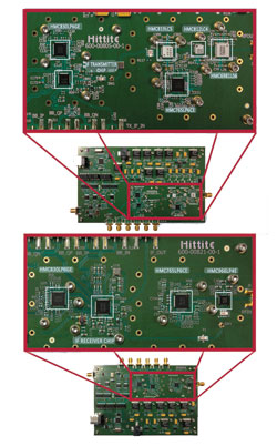
The functional diagram in Figure 1 is an example of how Hittite’s microwave chipsets can be used to realize a microwave radio transceiver solution for the licensed 18 GHz point-to-point radio band (17.7 to 19.7 GHz). The 18 GHz transmit chipset reference design converts the 350 MHz IF frequency from the indoor unit (IDU) to an 18 GHz transmit signal at the antenna.
At the heart of the transmit chipset is a highly integrated IF transmitter chip, HMC7436LP5ME. It is designed for high linearity operation, supports modulations up to 4096-QAM and is housed in a compact, 32-pin 5 × 5 mm standard QFN package. The HMC7436LP5ME IF transmitter chip, shown in Figure 2, takes the industry standard 300 to 400 MHz IF input signal and converts it to a 0.85 to 4 GHz single-ended RF signal at its output. The IF input power range is from –28 dBm to +3 dBm. To equalize for input signal cable losses, HMC7436LP5ME provides 32 dB of digital gain control in 1 dB steps, while an analog VGA controls the transmit output power continuously from –20 dBm to 0 dBm.
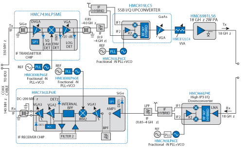
Figure 1 Complete 18 GHz transmit/receive chipset reference design.
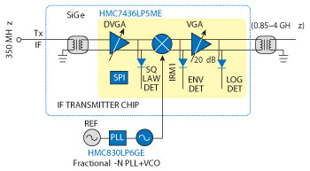
Figure 2 HMC7436LP5ME IF transmitter chip block diagram.
The HMC7436LP5ME also features three integrated power detectors. A square law detector after the DVGA is used to set the power level into the mixer, the envelope detector after the mixer can be used for calibration, and the log detector is for fine output power adjustment through the analog VGA. Analog baseband IQ interfaces (not shown) are also provided to support FODU direct modulation configurations. In this baseband configuration, the HMC7436LP5ME includes four integrated and configurable lowpass reconstruction filters covering channel bandwidths of 14, 28, 56 and 112 MHz with bandwidth calibration. The IF transmitter chip is configured via a three-wire SPI interface.
The LO for the IF transmitter chip can be taken from the HMC830LP6GE wideband fractional synthesizer, which covers 25 to 3000 MHz, or the HMC833LP6GE, which covers up to 6000 MHz.
The HMC819LC5 in the transmit chain is a sub-harmonically pumped I/Q transmitter that incorporates a frequency doubler in the LO path, a pair of double balanced mixer cells, and a single-ended driver output amplifier. This high linearity I/Q transmitter is rated for microwave frequencies from 17.7 to 23.6 GHz, and provides 15 dB conversion gain and 35 dB of sideband rejection. The HMC819LC5 I/Q transmitter is followed by the HMC812LC4 voltage variable attenuator (VVA), which is used to set the output power level of the transmit chain. The HMC812LC4 is rated from 5 to 30 GHz and provides a continuously variable attenuation range from 0 to 30 dB. Implementing a VVA in this section enables the radio to dynamically adjust its output power depending upon the environmental conditions. Following the VVA, the HMC6981LS6 power amplifier delivers 2 W of output power, representing one of Hittite’s best-in-class microwave radio linear power amplifiers. The HMC6981LS6 covers the 15 to 20 GHz frequency band and delivers 26 dB of gain, +33.5 dBm output P1dB and +43.5 dBm output IP3. The amplifier also features an integrated, temperature-compensated power detector, which may be used in a closed loop circuit to maintain constant output power over temperature variations.
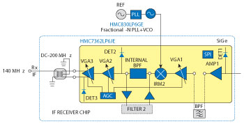
Figure 3 HMC7362LP6JE IF receiver chip block diagram.
The LO for the HMC819LC5 I/Q transmitter is provided by the HMC765LP6CE fractional PLL/VCO, which covers 7.8 to 8.8 GHz with closed loop phase noise of –101 dBc/Hz at 10 kHz offset. Hittite Microwave offers the widest portfolio of fully integrated PLL-based microwave frequency synthesizers and VCOs with best-in-class phase noise and spurious performance.
In the receiver section, the HMC966LP4E shown in Figure 3 is a sub-harmonically-pumped low noise downconverter (LNC) that is rated for input frequencies from 17 to 20 GHz, and incorporates a low noise amplifier and frequency doubler in the LO path and an image reject mixer. The HMC966LP4E accepts a sub-harmonic LO input between 7.5 and 11.75 GHz, supports an IF of DC to 3.5 GHz, and achieves 40 dBc image rejection and a low 2.5 dB noise figure. Following the LNC is the highly integrated IF receiver chip HMC7362LP6JE, which converts the downconverted receive signal to a 140 MHz IF that is fed back to the IDU. As shown in Figure 3, it includes three VGAs to achieve 80 dB of analog gain control, three power detectors, a programmable AGC block, as well as selectable integrated bandpass filters (14, 28 or 56 MHz bandwidth). The filters can also be bypassed to allow for off-chip filtering of other user-defined bandwidths.
The HMC7362LP6JE IF receiver chip is designed for high linearity operation, supporting modulations of up to 4096-QAM and bandwidths up to 112 MHz. It supports an RF input range from 0.8 to 4 GHz and is housed in a compact, 40-pin 6 × 6 mm standard QFN package. The HMC7362LP6JE also supports baseband IQ interfaces after the mixer so that the chips can be used for direct modulation in the FODU configuration.
For all other microwave radio bands, designers can select chipsets to realize all of the licensed microwave radio bands from 6 to 42 GHz. Hittite has a large selection of components available for microwave radio applications. The IF transmitter and receiver chips HMC7436LP5ME and HMC7362LP6JE support all of the standard microwave frequency bands from 6 to 42 GHz.
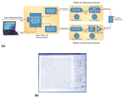
Figure 4 18 GHz microwave link demonstration setup (a) and constellation view (1024-QAM).
18 GHz PtP Microwave 1024-QAM Link Demo
To validate the performance of the Tx and Rx chipsets, an 18 GHz point-to-point (PtP) microwave radio demonstration link was set up. Hittite Microwave and Xilinx- worked together to develop the demonstration setup shown in Figure 4. The demonstration setup combines the Xilinx XPIC_R1 modem with 18 GHz microwave Tx and Rx sections configured on PCBs using Hittite’s chipsets. The connections between the Xilinx and Hittite boards are the conventional 140 MHz Rx IF and 350 MHz Tx IF. The Xilinx XPIC_R1 is running the complete PtP modem IP, named MWR1024RS, on a Kintex-7 FPGA. This full-featured, high-performance modem IP from Xilinx is capable of up to 1.0 Gbps raw data throughput with 1024-QAM modulation. The user data payload is streamed over a Gigabit Ethernet link in the end system. The demonstration platform relied on the Xilinx MWR1024RS PtP Modem GUI to control the boards and display the received signal constellation and key link statistics (see Figure 4b). More information on the MWR1024RS PtP modem IP is available from Xilinx.
The Hittite synthesizer and IF chips were programmed using a three-wire SPI port. The synthesizers were programmed for an IF frequency of 1740 MHz for Tx and 1840 MHz for Rx, while the IF chips were programmed for channel bandwidth, gain and interface type (IF). The Tx modem was configured to transmit a 1024-QAM modulated signal in a 30 MHz channel, and the transmitter chip gains were set to achieve +20 dBm RF signal output power. A variable RF attenuator was connected between the transmit and receive RF ports to simulate the link path loss that would be realized in a deployed microwave radio link. As the RF attenuator was varied, the AGC in the Rx IF chip maintained the appropriate IF output power to the modem to maintain optimal link performance. The modem was able to measure a Bit Error Rate (BER) of better than 10-9 over a wide range of attenuation settings. The digital modem can demodulate even lower signal levels as it supports modulation orders down to QPSK – which may be changed on-the-fly.
Hittite Microwave continues to provide innovative, high performance, Antenna-to-Bits microwave radio solutions covering all bands from 6 to 42 GHz, while supporting both split-mount and full ODU style microwave radios. The IF transmitter and IF receiver chips HMC7436LP5ME and HMC7362LP6JE provide a very high level of integration, support all of the standard microwave frequency bands from 6 to 42 GHz, and form the core of these compact, high performance microwave radio chipsets.
Hittite Microwave and Xilinx have successfully demonstrated a complete modem with 1024-QAM modulation in a 30 MHz channel over an 18 GHz microwave link. The BER of the complete modem was better than 10-9 over a wide range of attenuation settings. The IF transmitter and IF receiver chips are also capable of supporting modulations of 2048 and 4096-QAM.
Hittite Microwave Corp.,
Chelmsford, MA,
txrx@hittite.com,
www.hittite.com