
Phase noise measurements fall under two categories: absolute and additive (residual). Absolute phase noise measurements are typical of oscillator or LO system level noise. Additive phase noise measurements are more specific, measuring the additive noise of an individual component or subsystem. Additive noise measurements are typically at a lower level and a more difficult measurement than absolute, requiring careful measurement setup and calibration. While the setup involves traditional microwave plumbing, the calibration can be tedious and prone to significant error. Holzworth Instrumentation’s HA7000B Series of phase noise analyzers addresses this problem by completely automating the calibration as well as an option for automating the setup.
Holzworth Instrumentation’s HA7000 Series phase noise analyzers were designed to optimize measurement speed and low noise floors, while being highly intuitive to set up and operate. The high level of automation was driven by the customers’ requirements to transition phase noise testing from R&D to the manufacturing environment while maintaining the low noise expected in R&D.
In response to customer requests to measure both absolute and additive phase noise with Z540 traceability, Holzworth has released revision B of the HA7000 Series. The revisited design for the HA7062B and HA7402B include: a more advanced front end, an external power supply for cleaner spurs (also allowing for powering the analyzer via a 12 V battery), and a Z540 traceable calibration. Most significantly, it has introduced fully automated additive phase noise measurements.
Using external HX series components designed specifically for the HA7062B and HA7402B, the calibration process has become completely automated. By using calibrated and traceable external components, the Z540 traceability is extended from absolute measurements to additive phase noise measurements. Using the advanced capability of the instrument, the measurement is both automated and accurate.

Figure 1 Fully automated, narrowband test setup.
HA7000 Cross Correlation Performance Advantage
Additive phase noise measurements share some common issues with absolute phase noise measurements. Problems such as port to port isolation and match in traditional instruments can lead to false readings by allowing the independent branches in the cross correlation system to not be independent enough for cross correlation theory to hold true. Depending on the setup, this can lead to either false measurements being high or low. To be confident in the data, the port match and port to port isolation need to be as close to as ideal as possible — not unlike a spectrum analyzer or network analyzer. The HA7000 Series typically has better than –20 dB return loss and isolation greater than 80 dB. Internal to the instrument, attention to detail involving ground loops, spurious and shielding provides confidence that the raw data reflects the true performance of the DUT. Without tedious attention to these performance parameters, the cross correlation function may be ineffective at accurately isolating the noise due to the DUT only.
Additive Phase Noise Test Setups
Additive phase noise of components and subcomponents give designers and manufacturers valuable insights to the performance of their systems. While absolute phase noise (oscillator or LO noise) can provide the user with the overall performance of a source or total system, additive phase noise focuses the noise contributions of individual two-port elements. The results can help to troubleshoot or predict overall system performance, similar to cascading S-parameters or calculating noise figure. Oscillator designers can even isolate the effect of different amplifiers on the overall noise.
Proper calibration of the additive phase noise system has traditionally been a manual process that is not extremely difficult, but even a small error can lead to erroneous results. The greatest challenge in the calibration is calculating the phase detector constant in relation to a known phase shift. The HA7000 Series phase noise analyzers feature a series of checks involving the internal frequency counters and power meters in conjunction with the new external calibration standards. To aid measurement setup, the software includes an active quadrature monitor for visual feedback.
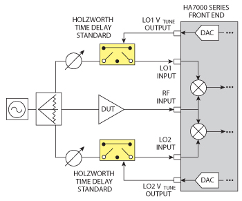
Figure 2 Automated, broadband test setup.
Two different external calibration standards are available. The first is a narrowband electronic phase shift calibration standard that adjusts the instrument into quadrature (where phase detection occurs) and performs full calibration. The second is a broadband time delay calibration standard where the user uses the software quadrature monitor to achieve quadrature and the time delay calibration standard is used to calibrate the instrument.
Narrowband, Integrated Phase Shift and Calibration
The first calibration standard setup incorporates a pair of Holzworth electronically (system) tuned phase shifters. In this scenario, both quadrature adjustment and calibration is fully automatic. As shown in Figure 1, the test system setup includes a frequency source, a three-way power divider and two Holzworth Electronic Phase Shifter Calibration Standards. The user introduces a DUT with an appropriate power level set and simply selects “acquire” on the analyzer’s GUI. The software takes over and monitors input frequency and power, then automatically adjusts each phase shifter to optimize conditions for phase lock and calibration. If any out of spec conditions occur, a warning message will appear.
The Electronic Phase Shifter Calibration Standards are sold in matched pairs and are for narrowband applications, optimized for frequency measurement offsets of 10 Hz to 1 MHz, but will operate down to a 1 Hz offset. Each calibrated pair is narrowband and may be ordered at any frequency. A range of standard models are available from Holzworth to cover common frequencies.
Broadband, User Supplied Phase Shifter, Automated Calibration
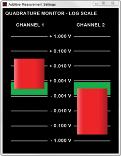
Figure 3 Holzworth quadrature monitor interface.
The second additive phase noise test setup automatically calibrates the system over a broad range of frequencies. It is up to the user to provide the necessary phase shift for quadrature. As mentioned previously, the software includes a log scale quadrature monitor to assist the user with setting exact quadrature. As shown in Figure 2, the test system configuration again includes a frequency source and a three-way power divider. The phase shift is performed manually, typically with a mechanical phase shifter. Calibration is automatic using a Holzworth time delay calibration standard.
Once the user has the DUT in place, the log scale Holzworth Quadrature Monitor (see Figure 3) is used to monitor the quadrature variation of each LO channel, while making small adjustments to each phase shifter. Once the quadrature of each channel is set to inside the target range, the user simply selects “Acquire” and the system automatically calibrates and begins taking data.
The broadband Time Delay Calibration standards are also Z540 traceable standards that are available as a calibrated set. They are optimum for either broadband work where mechanical phase shifters are available or when the very lowest noise at close to the carrier is required. Mechanical phase shifters offer a performance advantage over electronic phase shifters close to the carrier when the lowest noise floors are required. The reduced noise floor is a trade-off for complete automation.
Additive Test Setup Example
The block diagram for a typical phase noise measurement setup is shown in Figure 1. In a traditional system, the phase shifters are mechanical and the calibration is manual, relying on the operator’s experience with the system. In this scenario, a pair of Holzworth Electronic Phase Shifter Calibration Standards move the system into quadrature and automatically calibrate the test setup prior to each measurement. A photograph of the system setup configured to demonstrate the noise floor of the additive test system is shown in Figure 4.
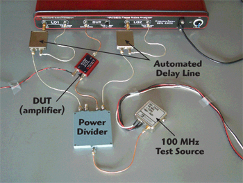
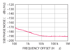
Figure 5 Test system noise floor at 100 MHz.
Additive phase noise measurements allow the measurement setup and system noise floor to be accurately measured under a given condition. Figure 5 shows the measurement noise floor of the Holzworth HA7402A system for this setup. This evaluation is performed at fc=100 MHz and the power is +15 dBm. In this scenario, 1000 correlations are used to reduce the noise floor, approaching the limit of the system. At 10 correlations, the noise floor is approximately –180 dBc/Hz (10 kHz offset). At 100 correlations, the noise floor had reached –185 dBc/Hz (10 kHz offset). At 1000 correlations, the noise floor had reached a floor of approximately –190 dBc/Hz (10 kHz offset). If mechanical phase shifters are used with the Time Delay Calibration Standards, a much lower noise close to the carrier can be expected.
The HA7000 Series has fully automated a difficult and sensitive measurement in an easy to use system. Like the absolute phase noise of high performance sources, additive phase noise is becoming an important evaluation parameter for two-port devices as they influence the overall phase noise of a system. The Holzworth HA7000 Series phase noise analyzers now include valuable additive phase noise features that automate the residual phase noise measurement by way of an intuitive interface. The revised designs couple versatility and ease of use with NIST traceable accuracy.
Holzworth Instrumentation,
Boulder, CO
(303) 325-3473,
sales@holzworth.com
www.holzworth.com