
 | |||
The primary motivation for using a system simulator is to establish the right system architecture and formulate suitable specifications for each of the underlying components. Accomplishing this goal helps companies to reduce time-to-market by eliminating iterations and rework, and to reduce system cost by ensuring that components are not over-specified and thus unnecessarily expensive. The sooner the engineering team has an accurate understanding of system performance before committing to hardware, the faster they can move the product into manufacturing and ultimately into the hands of the consumer.
Visual System Simulator2004™ (VSS) is comprehensive software for the design of complete, end-to-end communications systems. VSS uses an advanced time-based simulation engine tightly coupled with AWR’s Microwave Office™ circuit simulation tool. These two powerful products are integrated in the AWR Design Environment™, which enables systems and circuit designers to work together within a single environment to perform interactive, top-down analysis of analog and digital communications systems.
VSS2004 technology enables designers to easily make critical system performance measurements, accurately analyze the impact of RF components on modulated signals, and make cost-effective “trade offs” between system specifications and circuit specifications. VSS is built on a complex envelope, data-driven simulation engine, providing blazing simulation speed and offering an extensive selection of behavioral blocks for wireless communications systems design engineers.
VSS2004 software can incorporate either high level behavioral models or detailed transistor-level circuit designs from Microwave Office software. It also offers seamless integration with TestWave™ software, AWR’s instrument interface, enabling engineers to perform analysis at the system level, where hardware measurements are incorporated through a bi-directional link to popular test and measurement equipment.
VSS2004 effectively gives the entire engineering team the “big picture,” including the RF impairments in the presence of complex modulated signals. The solution reduces time-to-market by providing a single integrated platform wrapped in an intuitive interface. With VSS, users can transcend the system hierarchy and easily move from a high level of abstraction down to a detailed level — from simulations that include layout parasitics to the incorporation of measured data read in directly from test instrumentation.
The company takes great pride in its customer responsiveness and listens closely to the needs of the consumer. As a result, customer-requested features are continually added to the product line and the products enhanced in a relatively short time by fully utilizing modern software technology. Several key new features have been added to VSS in 2004.
RF Budget Analysis
RF Budget Analysis is a unique new solution that enables designers for the first time to calculate cascaded performance of the RF link. This new addition to VSS system measurements takes the software to a higher level of RF link system analysis.
Traditional RF/analog system analysis commonly requires several tools to achieve a complete analysis of end-to-end performance. For example, the engineering team may use one tool for error vector magnitude (EVM) measurements and another for calculating cascade noise figure (NF) and output IP3 (OIP3). With VSS2004, engineering teams now have an efficient and comprehensive platform for making RF cascade calculations at interior points of the RF link to perform an EVM measurement, all within a single system diagram, as shown in Figure 1. Working in one environment provides a seamless flow of information between traditional systems engineers and RF/analog engineers.
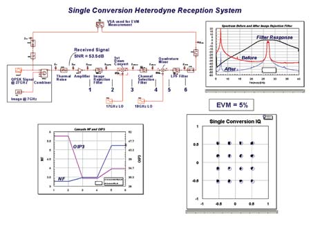 | ||
| Fig. 1 RF Budget Analysis and EVM. | ||
With the integration of RF cascade calculations into VSS2004, not only do all of the RF VSS behavioral models now include an NF parameter, but the software can also automatically extract IP3 and NF parameters from Microwave Office and Analog Office™ circuit designs. Designers can start their VSS design with RF behavioral models, and as the design process matures, they can replace these models with actual circuit designs and continue with the same RF link to perform cascaded measurements.
RF Budget Analysis measurements allow engineers to specify either a unique frequency or a set of frequencies over which to make the measurements. RF cascade calculation results can be displayed in a tabular or graphical flow format. The measurements can be used for modeling the noise, gain, IP3, signal-to-noise ratio (SNR), intermodulation performance and compression characteristics of a system of cascaded components.
VSS2004 and RF Budget Analysis are powerful tools that give an engineering team the ability to perform trade-off studies in order to balance performance parameters such as gain distribution, spurious levels and receiver sensitivity. Designers can now discover systems deficiencies quickly and eliminate design turns.
PLL Simulation Blocks
Phase lock loops (PLL) are an integral part of communications systems. The integration of dedicated behavioral PLL blocks into VSS2004 provides the ability to interactively investigate the dynamics of frequency synthesizers, frequency/phase modulators and frequency/phase demodulators.
The PLL models are designed to give engineers access to high level parameters such as the charge-pump current and the voltage-frequency gain (Kvco) of the voltage control oscillator (VCO). Users can choose from several behavioral filter models that are representative of both passive and active topologies. After the behavioral loop filter parameters have been determined, engineers can take the design a step further by replacing this filter with a Microwave Office circuit design, as shown in Figure 2.
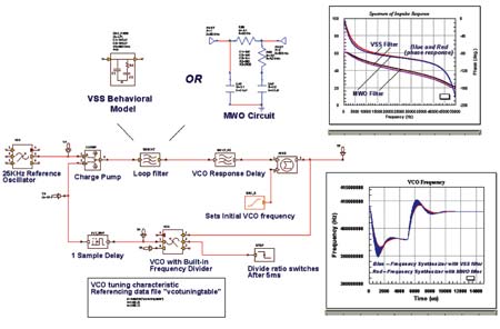 | ||
| Fig. 2 Frequency synthesizer. | ||
Through simulations, engineers can establish practical PLL design guidelines. For example, they can determine the PLL’s stability, phase margin, open- and closed-loop frequency response, bandwidth, and pole locations. Transient simulation (both fast and accurate) can be performed to visualize settling time or an abrupt change in the divide-by-N ratio.
Using VSS2004 blocks, the designer can account for many of the non-idealities encountered in practical PLL implementations. The nonlinear tuning table of a VCO can be imported into VSS2004 together with its phase noise. Ultimately, the best loop bandwidth, phase noise, transient response and phase margin can be determined by working with the VSS2004 PLL behavioral blocks.
VSS2004 Core Enhancements
Core models such as a lookup table, variable gain amplifier (VGA) and align are found in VSS2004. One use of the lookup table is to simulate the function of a variable voltage attenuator (VVA) or, more generically, for simulating a nonlinear transfer function. The VGA model can be used to analyze the behavioral characteristic of an automatic gain control (AGC) system. The align block analyzes two signals, a reference signal and a degraded version of the reference signal, for timing alignment, and gain and phase distortion. The signals are then delayed as necessary to time-align the signals on output. The corrupted signal is gain- and phase-compensated to minimize the effects of gain and phase distortion. Typically this model is used prior to making an EVM measurement.
Additional signal sources intended for use when performing RF link analysis and/or conformance testing have been added to the extensive list of VSS2004 models. The new models are similar to the existing 802.11a/b/g signal generators in that they use the proper modulation and have the correct spectral qualities. The new models consist of digital video broadcast (DVB) and code division multiple access 2000 (CMDA2000) signal sources. Engineers can also take advantage of the wide range of VSS primitive models such as forward error correction (FEC) models, and add additional features to these signal sources. A third-generation (3G) design studio exists for engineers who want to create 3G wideband CDMA (WCDMA) frequency division duplex (FDD) “bit accurate” signals.
VSS2004 measurements have been enhanced as necessary. Root raised cosine (RRC) filtering is added to the adjacent channel power ratio (ACPR) measurement window to meet the needs of engineers performing 3G WCDMA FDD conformance testing. The direct importation of spectral masks has also been added to the VSS measurement window. This feature is particularly useful for engineering teams performing conformance tests using today’s wireless communication signals. In addition, through the use of systems annotations, engineers can monitor at each node in the system such metrics as the SNR, signal power and signal delay.
The company continues to enhance the integration of VSS with Microwave Office through the AWR Design Environment. VSS2004 provides users with a seamless connection to incorporate directly into the system diagram both oscillator phase noise and mixer spur measurements obtained from circuit designs. Upon completion of an oscillator’s phase noise analysis in Microwave Office, its single-sideband phase noise profile can be directly imported into the VSS phase noise model. In VSS, for example, the effect of the phase noise on bit error rate (BER) performance can be determined. A circuit-level mixer design can be accurately simulated in VSS by exporting the Microwave Office spur analysis results as an MxN spur table into the system “file based” mixer, as shown in Figure 3. In addition, the VSS frequency-dependent nonlinear model has been improved, allowing the simulation of a frequency-dependent amplifier design in Microwave Office to be realized at the system level.
 | ||
| Fig. 3 VSS mixer. | ||
Adaptive behavioral models such as least mean square (LMS) and recursive least square (RLS) equalizers have also been added. One use of an equalization system is to compensate for transmission-channel impairments such as frequency-dependent phase and amplitude distortion. Besides correcting for channel frequency-response anomalies, an equalizer can be used to cancel the effects of multipath signal components. The resulting equalizer coefficients that are generated can be exported to external files to be used, for example, in a stand-alone finite impulse response filter (FIR).
VSS2004 supports AWR’s ongoing commitment to deliver to the engineering team a single design environment that allows for a true top-down analysis of analog and digital communications systems. This new software solution further reduces product development costs for designers of wireless telecommunications equipment, semiconductors, high speed computers, networking systems and other electronics-based products.
Applied Wave
Research Inc. (AWR),
El Segundo, CA (310) 726-3000, info@mwoffice.com.