
The frequency selective surface (FSS) has been the subject of extensive research for the last three decades. An FSS acts like a bandpass or bandstop filter at microwave frequencies. Extensive research has been done on bandwidth enhancement and the decrease of insertion loss, for example, but this work has been done mainly on planar FSSs. Very little work has been done on curved FSSs. The design of a dual-layer curved cylindrical FSS with the sharp roll-off and flat bandpass properties described here can reduce interference and increase channel capacity in a communication system.
The FSS is a spatial filter in the radio frequency range. It comprises a periodic arrangement of identical elements in a 1D or 2D array. Patch and aperture are two fundamental types. A vast amount of research has been done on planar FSSs because a unit cell of an infinite array can be used for the analysis and comprehensive study of the entire structure. The same approach cannot be taken for a curved structure as its extrapolation from a single unit cell is not possible because, for certain incident fields, element currents and scattering from the edges of the curved surface diverge significantly.1 Hence, the curved FSS is a mathematically complex structure and is difficult to analyze.
While wide bandwidth is the basic requirement for high speed communications, roll-off plays an important role in reducing noise and interference during the transition from the passband to the stopband. Good roll-off has been documented with aperture-type planar FSSs having Archimedean spiral and annular ring elements.2-4 Wideband and multiband aperture-type planar FSSs have been reported. A flat passband response with high roll-off has been achieved.5,6
A bandpass planar FSS with a square slot exhibited 2.7 GHz bandwidth with left and right roll-offs of 7.33 dB/GHz and 30 dB/GHz, respectively.7 A polarization-insensitive FSS was designed using a square unit cell loaded with two pairs of ring slots and one split-ring slot pair.8 The structure demonstrated good transmission characteristics within the passband with a steep roll-off. These planar structures are excellent candidates for high performance passband FSSs and can be designed easily. The task of achieving high performance with sharp roll-off, wide bandwidth and low insertion loss, however, is not easy to realize in a curved structure, as the nature of the transmission curve entirely depends on the FSS element, the lattice and the degree of surface curvature.
The properties of curved FSSs have been studied using basic elemental structures like tripoles, circles and others.9-11 A design with a tripole element,9 resulted in reduced bandwidth for a curved structure as compared to a planar FSS. A sandwich radome wall investigation was carried out using a double square loop FSS structure.12 The conformal FSS resulted in enhanced bandwidth and high roll-off, however, no experimental validation was provided.
A spherical dome-shaped FSS with a radius of 50 mm demonstrated wideband performance but with a poor roll-off.13 The study of a single-layer hemispherical FSS with a novel-shaped element demonstrated a wide band response with an approximate roll-off of 9 dB/ GHz,14 while a double-layer ring slot planar and curved FSS exhibited a good bandpass response over a large angle of incidence.15
This article describes the design, simulation and measurement of a dual-layer semi-cylindrical curved FSS with concentric annular ring elements. The structure provides a wide passband response in X-Band. It can be used as a bandpass filter with 45 percent bandwidth which is almost the same for planar and curved structures. It demonstrates that an FSS can be designed to work on a curved surface and achieve a wide bandwidth, low insertion loss and sharp roll-offs at both band edges.
DESIGN
Figure 1 shows the unit cell of a dual-layer aperture-type planar FSS. Two concentric annular rings of different radii are periodically arranged in a metallic screen to configure both layers of the aperture. Aluminum foil paper is used as a metallic sheet and air is the dielectric. The periodicity of the FSS is 29 mm in both vertical and horizontal directions. An air gap of 7.6 mm between the two layers is determined to be optimum. The structure is simulated using Ansys HFSS. The two planar layers of the composite FSS are shown in Figure 2.
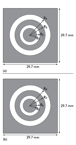
Figure 1 FSS unit cells: Layer 1 [R1 = 5.5, R2 = 8.75, R3 = 10 and R4 = 14 mm] (a), Layer 2 [R5 = 6, R6 = 8.25, R7 = 10 and R8 = 14 mm] (b).
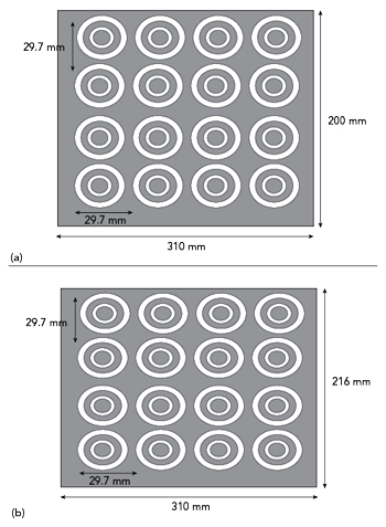
Figure 2 FSS layers: Layer 1 (a) and Layer 2 (b).
The dual-layer semi-cylindrical aperture-type FSS is designed, keeping the dimensions of the elements and periodicity like that of the designed planar structures. The radii of the inner layer and outer layer of the semi-cylinder are 100 and 107.6 mm, respectively, maintaining the optimized planar air gap of 7.6 mm. The length of the semi-cylinder is 310 mm. The dimensions of the semi-cylinder are limited, as simulation of the curved FSS requires high computational resources.
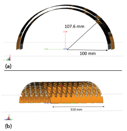
Figure 3 Semi-cylindrical FSS: front view (a) and side view (b).
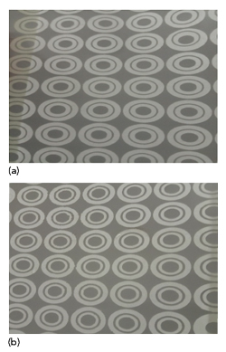
Figure 4 Fabricated FSS layers: Layer 1 (a) and Layer 2 (b).
Two views of the final dual-layer semi-cylindrical curved FSS design are shown in Figure 3. The design and simulation are done in Altair CADFEKO simulation software. The fabricated FSSs are shown in Figure 4. The measurement of both the planar and curved structures is done using a standard microwave test bench (see Figure 5).
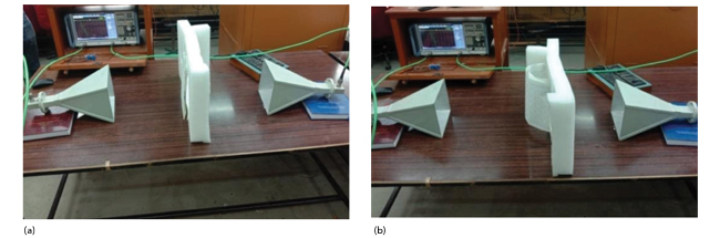
Figure 5 Measurement setup: planar FSS (a) and curved FSS (b).