

220 to 330 GHz lenses were not available at the time of this experiment, so 6-in. lenses were removed from a COTS G-Band Gaussian optics antenna assembly and 3D-printed fixtures were designed to mount the lenses to a track. A 3D-printed fixture was designed to mount the VDI converters, with careful consideration to align the center of the WR3.4 diagonal horn antenna with the center of the lens. Horizontal track mounts with hand brakes allow spacing adjustments between the diagonal horn antenna and the lens on the transmit and receive sides of the test setup.
QUASIOPTIC OTA TRANSMISSION
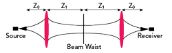
Figure 4 Quasioptic transmission, assuming the same lenses and feed horns for the source and receiver.
Figure 4 shows the concept of using lenses for quasioptic transmission. The radiating element of the transmitting source, a diagonal feed horn antenna sits at a distance Z0 from the lens, the quasioptical focusing element. A beam waist, which is the minimum in the beam radius, occurs at distance Z1 from the lens. The beam begins to diverge beyond the beam waist at Z1. A more rigorous description of quasioptic systems can be found in Quasioptical Systems: Gaussian Beam Quasioptical Propagation and Applications.2
Quasioptic Ota Signal Analysis At 285 GHz With 30 GHz Bandwidth
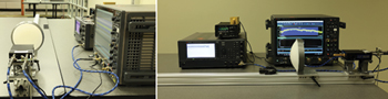
Figure 5 OTA quasioptic transmission at 285 GHz with 30 GHz bandwidth, receive side.
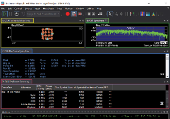
Figure 6 VSA Flex Frame demodulation results for quasioptic transmission at 285 GHz with 30 GHz bandwidth.
The receive side of the test setup in Figure 5 shows the receive lens, followed by a VDI WR3.4 diagonal horn antenna attached to the VDI compact WR3.4 down-converter. The final spacing between the transmit and receive lenses was 26.5 ft. (8 m) lens-to-lens spacing. Measurements for intermediate spacings from 3 to 13 ft. were also performed incrementally to achieve the final spacing. The E8257D PSG analog signal generator with option UNY provides a low phase noise LO at 21.666 GHz for the VDI down-converter. The E8257D PSG 10 MHz external reference is locked to the E8267D PSG 10 MHz reference output on the transmit side. The 285 GHz signal is down-converted to a 25 GHz IF (285 GHz RF - 260 GHz LO = 25 GHz IF). The 25 GHz IF is amplified by an external IF amplifier, then digitized with a UXR four-channel high performance 110 GHz oscilloscope and demodulated using VSA Flex Frame software. The UXR 10 MHz external reference is locked to the two PSGs. A laser source mounted on the receive track performs the initial alignment of the receive lens with the transmit lens. Power measurements used an N1913PM5B VDI-Erickson power meter with the WR3.4 diagonal horn antenna connected to the sensor head and WR3.4 waveguide taper.
Figure 6 displays the OTA demodulation results using VSA Flex Frame, showing the measured 16-QAM constellation and measured spectrum at 285 GHz on the upper traces in trace A and trace B. For the OTA measurement, the Flex Frame normalized channel delay spread increased relative to the conducted case to address increased OTA channel delay. The blue-shaded region of the spectrum shown in trace B measures the occupied bandwidth of 30.5 GHz. Trace C shows the composite EVM measurement of 9.2 percent. The lower trace, trace D, shows the VSA Flex Frame summary for the sync, SFD, CES, frame header and data payload frame allocations.
The VSA Flex Frame software was enhanced to perform a two-pass channel estimation to address these challenging channel scenarios in low SNR environments. The first pass uses pilots and preamble to perform synchronization and initial channel estimation. The second pass adds data payload to perform channel estimation with pilots, preamble and data payload symbols, minimizing EVM over the specified number of symbols in the result length field.
Changing the number of data payload symbols included in the EVM measurement impacts composite EVM. The least mean square (LMS) equalizer attempts to minimize the EVM over the number of symbols specified, which is 8000 for this measurement. Symbols are noisy because of low SNR over the 30 GHz bandwidth, so the LMS equalizer algorithm has a more difficult estimation process as the number of symbols increases.
SUMMARY
The 220 to 330 GHz frequency band is relatively uncharted territory and there are many unknowns in understanding what level of system performance is achievable. Few publications show system-level RF performance, such as EVM in this band with 30 GHz bandwidth. The results shown here illustrate the achievable system-level performance and key challenges. This article presents two examples to increase insight into the achievable system performance in the 220 to 330 GHz frequency band:
- Conducted EVM measurements with up to 30 GHz of occupied bandwidth for the 220 to 330 GHz frequency band provide insight into the best-case achievable EVM performance.
- Quasioptic techniques for an OTA point-to-point transmission at 285 GHz with 30 GHz occupied bandwidth provide insight into the achievable OTA transmission distance. A distance of 26.5 ft. (8 m) was achieved, as shown in a video demo of this test setup.3
References
- “6G: Going Beyond 100 Gbps to 1 Tbps,” Keysight, 2022, Web: https://www.keysight.com/us/en/assets/7121-1152/white-papers/6G-Going-Beyond-100-Gbps-to-1-Tbps.pdf.
- P.F. Goldsmith, “Quasioptical Systems: Gaussian Beam Quasioptical Propagation and Applications” Wiley-IEEE Press, 1998, Paper.
- Keysight Test Setup Video Demo.
To view the Keysight Test Setup Video Demo, please visit:
6G Testbed Over-the-Air Transmission using Sub-THz Quasi-Optic Techniques - YouTube at bit.ly/3JB1wWQ