
High-power signals with minimal phase noise are crucial for radar and communication systems, for phase noise is directly related to receiver sensitivity. At the heart of each system is an oscillator, which can be configured to have very low phase noise. However, oscillators tend to have low output power, so they often must be boosted by amplifiers. The addition of amplifiers presents other issues, most notably the addition of phase noise to signals passing through the system. This additive phase noise can mask a target or otherwise interfere with signal integrity and transmission.
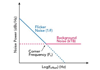
Figure 1 Phase noise contributors in oscillators.
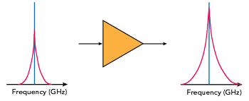
Figure 2 An amplifier's effect on phase noise.
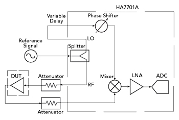
Figure 3 Phase noise measurement setup.
One serious issue faced by systems designers is quantifying the level of additive phase noise, since this parameter is challenging to measure. In this article, we discuss additive phase noise and the reasons why reducing an amplifier’s contribution to phase noise is important to a system’s performance. We also demonstrate the techniques needed to improve additive phase noise measurements across frequencies for reliable product classification. We further investigate the impact of amplifier type and compression level on additive phase noise and explore how the optimization of these characteristics can improve phase noise performance dramatically. Finally, we verify our findings through production testing and convey the ramifications for engineering design.
ADDITIVE PHASE NOISE
Phase noise refers to the stability of a signal’s frequency over time.1–3 Ideally, an oscillator produces a perfect sinusoid at a singular frequency -- which we call the carrier or desired signal -- that has zero phase noise. However, the presence of noise causes all oscillators to behave in a non-ideal fashion. The two main sources of phase noise are background noise and the up-conversion of near DC (1/f) flicker noise (see Figure 1).
As the figure shows, background noise is constant over time and dominates the high frequency spectrum away from the source frequency. The power of the background noise, PN, is defined as

where k is Boltzmann’s constant, B the frequency bandwidth and T the temperature of the system. The background noise is, therefore, related to operating conditions in addition to the oscillator itself.
The other type of phase noise, the up-conversion of flicker noise, manifests as a skirt around the desired frequency, rather than a single tone in the frequency domain. As shown in Figure 1, flicker noise decreases linearly on the logarithmic scale until it reaches the corner frequency, which is where the spectrum becomes dominated by the high frequency background noise. Since this second source of phase noise is produced close to the carrier, it causes significant signal interference.
In a system requiring high sensitivity, an oscillator with low absolute phase noise is an ideal signal generator. However, many applications require higher power levels than a standard signal generator can produce, so amplification must be introduced into the transmit chain. Rather than solely amplifying the oscillator’s carrier signal and associated phase noise skirt, though, the amplifier adds phase noise of its own (see Figure 2). As shown in this figure, the width and height of the output skirt increases due to the additive phase noise of the amplifier. If an amplifier’s phase noise is too high, it can overpower the noise associated with the oscillator, eliminating the benefits of a low noise oscillator. As a result, properly characterizing and measuring the phase noise of amplifiers and other components is important to ensure the successful performance of RF systems.
ADDITIVE PHASE NOISE MEASUREMENT
Additive phase noise can be notoriously difficult to measure because it is often 30 to 40 dB lower than the absolute phase noise of the reference signal.3,4 Therefore, phase cancellation is used to perform the measurement. This method has been examined by Breitbarth and Koebel5 and implemented in commercially available phase noise analyzers, such as the Holzworth Instrumentation HA7701A used in this study. A block diagram of the measurement setup is shown in Figure 3, including the internal components of the analyzer. The block diagram shows how the phase cancellation measurement system isolates the amplifier additive phase noise.