
From the electrical design parameters, Figures 6, 7 and 8 provide dielectric substrate and DR topologies to achieve the optimal, i.e., maximum, effective Q-factors for the oscillating system at a given frequency. The results were verified using ANSYS, the finite-element electromagnetic simulator. The analysis determines the geometric size of the conductor and its position on the polycore substrate, as well.
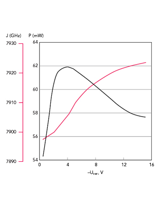
Figure 9 Power and frequency vs. tuning voltage.
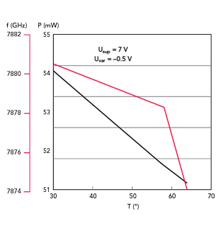
Figure 10 Power and frequency vs. temperature.
MEASUREMENTS
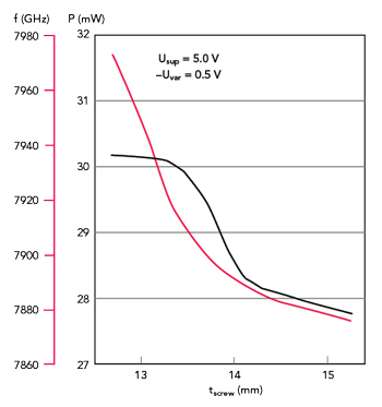
Figure 11 Power and frequency vs. tuning screw position.
Experimental results show that conditions for oscillation are met over a wide range of circuit parameters, i.e., up to 30 percent from the calculated values. This includes DR position with respect to MSL conductor length, resonant frequency, DC bias voltages from 5 to 9 V and VD tuning voltage. DRO characteristics versus VD tuning voltage, temperature variation and mechanical tuning screw position are shown in Figures 9, 10 and 11, respectively.
DRO phase noise heavily depends on the oscillation system Q-factor and, more precisely, on the Q-factor of the resonance curves of the coupling frequency where oscillation occurs. Therefore, considering the low Q-factor of the VD - which does not exceed 500 - the phase noise depends mainly on the required frequency tuning range. The measured phase noise for the 40 MHz tuning range is about ‐80 to ‐85 dBc/Hz at 10 kHz offset from a 10 GHz oscillation frequency. For the 10 MHz frequency tuning range, the phase noise drops to ‐92 dBc/Hz at the same oscillation and offset frequencies (see Figure 12). This tuning range is sufficient for a PLL to compensate for temperature frequency drift, which should not exceed the electrical tuning range.
CONCLUSION
A method for the analysis of complex microwave oscillating systems enables the development of a DRO that meets phase noise and frequency tuning range requirements.n
Acknowledgments
The authors would like to thank Dr. Alexander Chenakin of Anritsu Company for his review and valuable feedback.
References
- A. V. Bunin, S. V. Vishnyakov, V. M. Gevorkyan and J. A. Kazantsev, “Design of an Oscillator System for Millimeter-Wave Generator,” Proceedings of the 15th International Crimean Conference, September 2005.
- A. V. Bunin, S. V. Vishniakov and V. M. Gevorkyan, “Design of a Millimeter-Wave Oscillator,” (in Russian), Electronics NTB, No. 6, 2008, pp.106–111.
- Miteq, internet resource, Web. www.nardamiteq.com/.
- Eravant, internet resource, Web. www.eravant.com/.
- Microwave Communications Laboratories Inc., internet resource, Web. www.mcli.com/.
- Nexyn Corporation, internet resource, Web. www.nexyn.com.
- Raditek International, internet resource, Web. www.raditek.com.
- A. Gorevoy, “A Low Noise Oscillator Based on a Conventional Dielectric Resonator,” Microwave Journal, Vol. 56, No. 11, November 2013, pp. 84–94.
- U. L. Rohde and A. K. Poddar, “DROs Drop Phase Noise,” Microwaves & RF, January 2013.
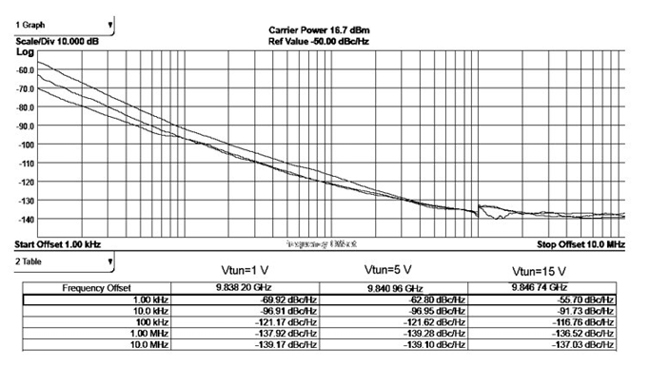
Figure 12 Phase noise performance.
Vladimir M. Gevorkyan received an engineering degree from the Moscow Power Engineering Institute (National Research University) in 1971 and a PhD in electrophysics in 1979. Since then, he has been teaching at the Moscow Power Engineering Institute and is also engaged in research in the field of electrophysics and microwave technology. Currently he is a professor and the head of the Laboratory of Electrophysics.
Yuri A. Kazantsev received an engineering degree from the Moscow Power Engineering Institute in 1970 and a PhD in electrophysics in 1976. Since then, he has been working and teaching as a professor at the Moscow Power Engineering Institute. His research interests are in electrophysics and microwave technology.