
A multi-layer dielectric resonator antenna (DRA) with a coaxial feed has a wide radiating and impedance bandwidth of 43 percent, from 8 to 12 GHz, thereby covering the entire X-Band. A single DRA exhibits a high gain of 8.2 dB at 10 GHz with an efficiency greater than 95 percent over the entire band. The single DRA includes a coaxial feed and a metal reflector cavity. The dielectric portion comprises an inner layer with a dielectric constant of 10.5 and an outer layer with a dielectric constant of 2.1. Prototypes of single DRAs are fabricated with unit cell sizes of 20 × 20 mm and 22 × 22 mm. RF measurements of single DRAs agree closely with simulations. Measurements of a 5 x 5 steerable array including a Rotman-Turner lens for steering closely matches simulated results over the entire 8 to 12 GHz frequency range for multiple steering angles from 0 to 30 degrees. The 5 x 5 array has a measured gain of 21.5 dB at 10 GHz.
Antennas are critical parts of many electromagnetic (EM) systems since they couple near-field operation with far-field EM radiation. Most conventional antennas leverage current flow in metals to generate EM radiation, however metal antennas exhibit degraded efficiency at elevated frequencies due to the skin effect and metal roughness. In addition, PCB-based 2D metal antennas have limited bandwidth and gain.
DRAs are 3D antennas formed of low loss dielectric materials that provide efficient emission and reception of EM radiation. For DRAs, EM energy in the so called “near zone” is almost entirely supported by displacement currents, which in contrast to conductive currents, are not subject to skin effect. Also, in contrast to metal-based PCB antennas, DRAs operate based on the principle of exciting multiple resonant EM modes in the dielectric structure, which enables very efficient operation up to mmWave frequencies.
Furthermore, when properly designed, the extended 3D shape of DRAs enables inherent and efficient wideband radiation operation with consistently shaped radiation patterns over the entire operating band.
RADIATING AND NON-RADIATING MODES OF A DIELECTRIC RESONATOR
Dielectric resonator (DR) resonant modes represent different EM field distributions. Their mathematical representations are found as solutions to the Maxwell-Helmholtz equation under certain symmetries and boundary conditions. The symmetry defines the type of mathematical function and the boundary conditions identify the mode. For example, if the symmetry is spherical, cylindrical or rectangular, the solution to the Maxwell-Helmholtz equation will be spherical harmonics, Bessel functions or the usual sine and cosine functions, respectively.
The most common resonator is a cylindrical resonator, also referred to as a puck, operating in its fundamental transverse electric TE01δ mode, or its lowest resonant frequency. Because of the cylindrical shape and symmetry, all eigenstates or resonant modes are represented by Bessel functions of the first and second kind, inside and outside the resonator, where the boundary conditions are reflected in the mode index.
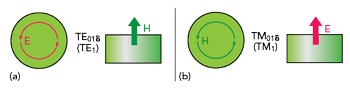
Figure 1 Electric and magnetic field distributions for the fundamental TE1 (a) and TM1 (b) unit cells.
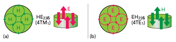
Figure 2 Electric and magnetic octupole modes, HE22δ (a) and EH22δ (b) in the Kobayashi representation.
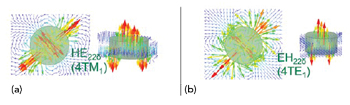
Figure 3 Simulated fields 4TM1 (a) and 4TE1 (b).
For example, for the TE01δ mode, the first index (0) is indicative of radial symmetry with no azimuthal cyclical structure. The second index (1) indicates that the electric field has one maximum, as represented by the Bessel function J1(kr), where k is the wavenumber along the resonator radius. More intuitively, the second index represents a Bessel type function with a half wavelength fitting within the radius of the resonator. Finally, the third index (δ) is associated with the mode structure along the z-direction normal to the cylindrical resonator’s top and bottom surfaces and is associated with the mode’s functional form along the z-direction. In the case of a puck in a “sandwich” configuration, where the dielectric is placed between two metal plates, δ = 1, and in the most general case, 0 < δ < 1.
The field structure of DR higher order modes is more complex and there are various ways to represent them. The method introduced above, based on φ, r and z coordinates, was proposed by Kobayashi-Senju and Zaki-Atia for the microwave regime and Snitzer in the optical regime.1-3 They also introduced the EH or HE designation for hybrid modes depending on which field, electric or magnetic, contributes the 0most dominant component in the z-direction.
In contrast, we propose an intuitive method of mode designation based on fundamental TE01δ and TM01δ transverse magnetic (TM) modes. We omit the first and the third index, therefore referring to the fundamental modes (i.e., unit cells) as TE1 and TM1, which represent magnetic and electric dipoles (MD and ED). Figure 1 illustrates the electric and magnetic field distributions for the fundamental TE1 and TM1 unit cells. For these fundamental modes, the field lines in the XY plane are parallel to the top and bottom surfaces of the cylindrical resonator and exhibit cylindrical symmetry, therefore they are very close to “pure” TE and TM modes.
Any higher order mode can be represented as a combination of multiple EDs or MDs. In our case though, TE or TM means “quasi” TE or TM. Examples of higher order modes are electric and magnetic octupole modes, HE22δ and EH22δ in the Kobayashi representation, which are shown schematically in Figure 2. Simulated fields corresponding to these modes are shown in Figure 3. In the proposed representation, they are referred to as 4TM1 and 4TE1, or four ED and four MD.
No matter how complicated the mode, it can be represented in terms of an even number of alternating electric or magnetic dipoles. The cyclic number, the first index in Kobayashi designation, which at the same time represents the azimuth structure of the Bessel functions, defines the number of alternating pairs in our representation. For example, for the HE22δ mode, the first index (2) means that there are two pairs (four nodes in azimuth), therefore four dipoles in our notation. The number of alternating dipoles is twice the first Kobayashi index.
The proposed method lacks the mathematical rigor of the Kobayashi method, but it offers a lot of advantages from the point of view of providing an intuitive understanding, a field visualization and an enabler for recalling the mode configuration. This representation is based on dipoles and is in complete alignment with the fundamental structure of electromagnetism and Maxwell equations, particularly the first two, which in principle represent infinitesimal electric and magnetic dipole structures.
The representation also aids in recollection of the mode-frequency hierarchy. More electric or magnetic loops imply more alternating dipoles, and hence a higher corresponding mode frequency. The method also provides a good understanding of the mode Q (quality factor), since the higher the number of dipoles, the tighter the fields are bound to the resonator and the closer the Q is to the inverse of tan(δ). The method also helps in providing and improving ways to excite the modes.
Most importantly, the method clearly shows the mode radiating properties, since the alternating dipoles represent evanescent modes, where their far fields cancel systematically and form very inefficient overall radiators. Only modes that are represented by unpaired dipoles can radiate efficiently, providing the two families of TE and TM unit cell modes: TE01δ (TE1), TE02δ (TE2), TE03δ (TE3), … TE0nδ (TEn) and TM01δ (TM1), TM02δ (TM2), TM03δ (TM3), … TM0nδ (TMn).
From now on, we omit the last index δ and call the modes simply TE01, TE02, TE03, … TE0n.
As mentioned before, TE modes have radial symmetry, therefore the system of the field lines can be supported by a half resonator on a metal surface (i.e., an electric wall), which also plays the role of electric mirror.
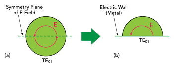
Figure 4 Electric field lines of one of the TE01 mode symmetry planes (a) and the field lines when the plane is replaced by an electric wall such as metal and half the resonator is removed (b).
Figure 4a shows one of the symmetry planes of the TE01 electric field lines. In Figure 4b, the plane is replaced by an electric wall, such as a metal, and half of the resonator is removed. Boundary conditions are still satisfied and the TE01 mode (together with all other members of TE family) is still supported. The half resonator can be a half cylinder, a half sphere (or dome) or a half ellipsoid.
This structure is used as the foundation of our designs because it offers an ideal way to excite and couple to DR TE modes and fully exploit their excellent radiation properties. The modifications in resonator shape and symmetry introduced by the electric wall suppresses DR modes with electric fields parallel to the ground. TM modes, as originally defined above, are also suppressed. However, the presence of the electric wall forming a ground surface creates favorable boundary conditions for a new family of modified TM modes. A strong electric field can be sourced from the ground and supported by the half resonator height, as shown in Figure 5.
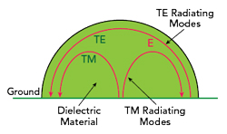
Figure 5 Electric field of TE and TM radiating modes in a dielectric half resonator.
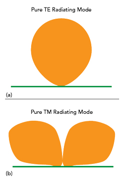
Figure 6 Radiation patterns of pure TE (a) and pure TM (b) radiating modes.
In fact, the radiating bandwidths of DRAs is determined by an interplay between radiating TE and TM modes (see Figure 6). As explained above, only TE and TM modes of radial symmetry, which are represented by unpaired dipoles, are efficient radiators. They also have very different radiation patterns: TE modes radiate maximally at boresight and minimally sideways (see Figure 6a), where TM modes radiate in exactly the opposite manner, minimally at boresight and maximally sideways (see Figure 6b).
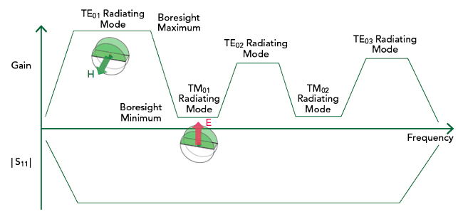
Figure 7 Representative alternating sequence of TE and TM modes vs. the frequency spectrum.
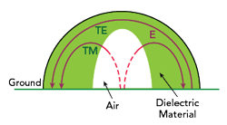
Figure 8 DRA design with an air center provides a wide radiating bandwidth with multiple TE modes.
For a typical DRA with a uniform dielectric constant spatial distribution, such as half cylinder DRA on a metal ground plane, TE and TM modes are present in the frequency spectrum in an alternating sequence (see Figure 7). The TE01 mode appears at the low end of the spectrum, followed by the TM01 mode, the TE02 mode, the TM02 mode and so on. Although such a DRA structure has a wide impedance bandwidth, the boresight radiating bandwidth is severely limited due to the alternation in the TE and TM modes in the spectrum.