
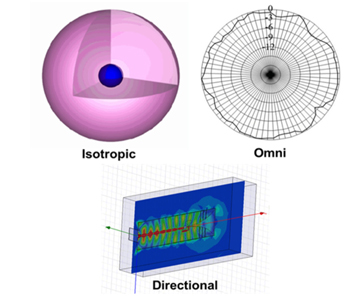
Antennas and antenna arrays serve as the “eyes and ears” for all wireless systems.1-6 According to IEEE Standard (145-1983),7 an antenna may be defined simply as “a means for transmitting and receiving radio waves.” The antenna serves as a transducer between the transmitter and the free space or between the medium and the receiver. In a broad sense, antennas may be classified into three categories, namely isotropic, omnidirectional and directional (see Figure 1). The isotropic antenna is a hypothetical concept of unity gain in all directions.3 It serves as a benchmark by which to measure practical antenna elements. An omnidirectional antenna is the closest realization of an isotropic antenna with almost constant gain in one plane of reference (azimuth or elevation),3 finding widespread use in broadcast applications. Directional antennas have higher directional gain and narrower radiation patterns (beams), desirable for applications like radio detection and ranging (radar) and point-to-point communications.1-6
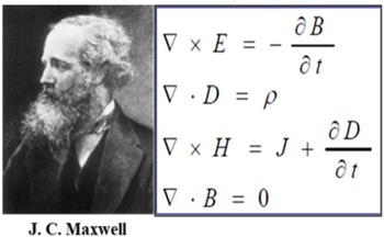
Michael Faraday, in 1830, introduced loop antenna as the part of his experiments studying the coupling of electric and magnetic fields.8 Later Heinrich Hertz8 discovered electromagnetic (EM) waves and designed a dipole antenna. In 1901, Guglielmo Marconi8 sent information across Atlantic Ocean using multiple vertical wires connected to the ground. This was the first use of antenna arrays.3 Maxwell3, 8 wrote the first treatise on EM theory congregating principles postulated by Oersted, Faraday, Gauss and others, popularly known as Maxwell’s equations (see Figure 2). It is shown by Maxwell that any accelerated charge radiates, and hence, an antenna may be defined as an EM device that controls the flow of the time varying currents; thereby, producing EM radiation.
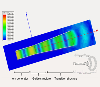
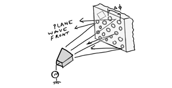
The antenna structure may be considered to have three sections, namely an EM generator, a guiding structure and a transition region (see Figure 3). Figure 3 is the result of a finite element method (FEM) simulation of a horn antenna showing the flow of rf energy in the respective sections. An EM generator inputs the EM wave into the guiding structure (the input of the flared horn), which directs it into the transition region. The transition region is a matching transformer, matching the impedance of guide with 377 ohms, the free space impedance. The EM wave escapes from the transition region into the free space, hence, causing the antenna to radiate.
Although the list of existing antenna types is too vast to summarize here, a few are selected and discussed, based on their commercial and military applications.
Antenna Basics
Antenna Qualifying Parameters (AQPs)
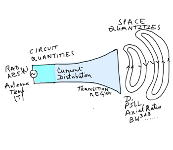
An antenna may be described quantitatively in terms of space and circuit parameters (see Figure 4). AQPs define the radiation and the impedance characteristics of an antenna, respectively, and are listed below:3
1. Antenna Gain, G and directivity (directive gain), D
2. Antenna temperature, T
3. Radiation resistance, R
4. Half power beam width, BW3dB
5. Pointing, look direction or scan angle
6. Sidelobe level (SLL) characteristics, such as peak SLL (PSLL), average SLL (ASLL).
7. Cross-polarization (x-pol) characteristics
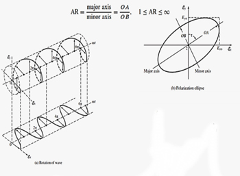
8. Axial ratio (AR)
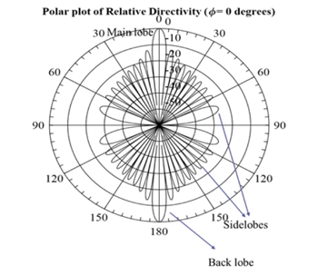
G measures directionality of an antenna pattern with reference to an isotropic antenna (G=1), thus, measurable in dBi (i for isotropic). It is different from D in the sense that it accounts for the various losses in conductors, space (radiation) and guides (dielectric or air),3 not included in directive gain, D. Hence, G is always less than D. BW3dB is the angular distance between the two – 3 dB points from the maximum, or peak, of the radiation pattern’s main beam. Look direction defines the direction in which the antenna pattern’s main beam is pointing while the array is scanning mechanically (using servo motors) or electronically (using digitally applied phase shifts to the elements of an array).4 Figure 5 shows a typical radiation pattern for a directional antenna. Apart from the main lobe (ML), which is desired, there are other unwanted lobes of much smaller magnitude in comparison to the ML, called sidelobes and characterized by SLL.
Antenna Classification
Figure 7 shows a classification of various antenna geometries. It includes wire antennas, traveling wave antennas, reflector antennas, microstrip antennas, log-periodic antennas, aperture antennas and others such as near field communications (NFC) antennas and fractal antennas. An individual antenna element may have a gain from 0 dBi (monopole) to 10-12 dBi (e.g. tapered slot antenna and helical) depending upon the type.
Depending upon specifications such as power handling, G, SLL, size, weight and volume, a class may be chosen for certain applications. Astronomical radio telescope antennas, for example, require very high gain and high-power handling capabilities along with open installations in large areas exposed to different, and often severe, topological and environmental conditions. These requirements are typically fulfilled by reflector antenna arrays.3 For platforms with limited real estate such as high altitude platforms (HAPS)2 and fighter aircraft, microstrip antennas are useful, being light weight, low profile and conformable in nature. Traveling wave antennas and log-periodic antennas are very useful for ultra-wideband and high-power handling applications. Fractal antennas are useful for realization of embedded antenna structures inside mobile handsets. The planar inverted folded antenna (PIFA) is a good structure for body-wearable conformal antennas applications. Antenna arrays are useful for applications such as radar, requiring high gain for detection at longer ranges and directional beams for target tracking.4

Antenna Arrays
Some applications require antennas with high gain, narrow BW3dB and electronic beam steering. These are requirements that cannot be met easily with a single antenna. For these applications, antenna clusters known as antenna arrays must be used.3 For a N-element array, G equals N times the single antenna gain, Go, i.e,

BW3dB is inversely proportional to G, i.e.,

typically for equally fed array elements.3
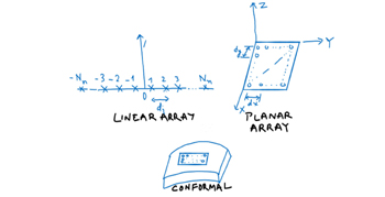
Antenna arrays can be classified into three main categories (see Figure 8):
- Linear antenna array (LAA), consisting of a one-dimensional cluster of antenna elements.
- Planar antenna array (PAA), consisting of a two-dimensional cluster of antenna elements.
- Conformal antenna array (CAA), consisting of a one- or two-dimensional cluster of antenna elements arranged conformally over a surface.
Generalized Expression for Directivity, D
D of an antenna array may be defined as9

where Po is the average radiated power and  is the maximum radiated power in a given direction.
The directivity and gain of antenna are related by

 represents the reflection coefficient of the antenna (circuit parameter) defining mismatch in the transition region of the antenna that matches the characteristic impedance of the guiding structure with that of free space for maximum transfer of energy to space from the antenna structure. Thus, G < D due to conductor, dielectric and mismatch losses.3, 9
The operational bandwidth (OBW) of an antenna may be defined as the range of the frequency points over which the antenna space and circuit parameters, measurable in terms of AQPs, are within desired limits defined by the user. The OBW may be classified in terms of radiation bandwidth and impedance bandwidth.3
Research Trends in AntennaS AND Antenna Arrays
Several current research areas include, but are not limited to:
1. Microstrip reflect arrays
2. Reconfigurable microstrip antennas
3. Body-wearable antennas
4. Multiple input multiple output (MIMO) antennas
5. Ultra-wideband antennas (UWB)
6. Metamaterial antennas
7. Connected array antenna
8. Windscreen antenna
9. Fractal antennas
10. Smart antennas
11. Defected Ground Structure (DGS)/electromagnetic band gap (EBG) Antennas
12. Conformal Antenna Arrays
13. Shared Aperture Antennas
14. Radar antennas
Microstrip Reflect Arrays
The concept was introduced by Berry et al.10 in 1963 using waveguide and was later realized using microstrip technology.11-16 Reflector antennas and phased arrays form the working principle for reflect array antennas (see Figure 9). The variation in size and geometry of planar antenna elements leads to an equivalent phase shift imitating parabolic reflector behavior. The reflector intercepts the impinged wave from a radiator placed at its focal point and scatters back the energy, which collimates due to its designed geometry, and forms a radiated beam. It has associated space loss and spillover loss. A phased array, on the other hand, includes an RF network including phase shifters, attenuators, amplifiers and feed network to receive/transmit energy; thus, there is an associated RF loss. A reflect array antenna overcomes these issues. A reflect array is a phase transformation structure where most of the elements are near resonance; hence, it provides an alternative to a conventional parabolic reflector antenna.
Samaiyar et al.14 discuss an application of reflect arrays for the realization of simultaneous transmit and receive operation at 5.8 GHz in the ISM band. Fukaya et al.15 describe a Tx and an Rx reflect array satellite antenna comprising multiple horns and a single-layer flat reflect array that radiates scanning beams along different directions in azimuth by virtue of polarization and frequency. A reflect array designed using tightly coupled dipole arrays (TCDAs) operates from 3.4 to 10.6 GHz.16 The microstrip reflect array antenna has been demonstrated to be a practical alternative to bulky reflector antennas and costly phased arrays.