
Evolution within the commercial aircraft market and changes to the most recent RTCA quality standards have led to a new set of challenges for testing nose-mounted radomes after they are repaired. To meet the changing needs of the sector, RTCA-DO-213A now requires testing with higher accuracy, within a shorter time and in less space.
Among the requirements for greater accuracy: assessment of transmission efficiency, beam width and secondary lobe levels through measurements in the Fraunhofer zone, i.e., r = 2D2/λ, where r is the measurement distance, D the diameter of the minimum sphere encompassing the antenna under test (AUT) and λ the wavelength. In previous versions of the standard, results were accepted with measurements at shorter distance. However, growing concern that radomes were not accurately assessed and inadequately transparent for the precision radar antennas below their surface drove the need for a compact, accurate and fast measurement solution.

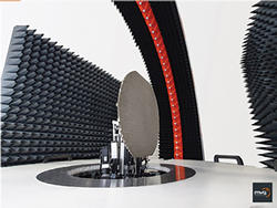
Figure 1 AeroLab near-field, multi-probe measurement system for testing nose-mounted aircraft radomes.

Figure 2 AeroLab positioners, gimbal and probe array.
Responding to this, MVG developed the AeroLab to supersede single-probe radome test systems with a faster, more flexible, compact system. The AeroLab is a near-field, multi-probe measurement system designed specifically to test nose-mounted aircraft radomes from 9.3 to 9.5 GHz and within an anechoic chamber no bigger than 4 m x 4 m x 5 m (see Figure 1). Composed of a quarter arch supporting an array of 31 precision, dual-polarized measurement probes, the system uses oversampling to recreate an infinite number of additional virtual probes. The positioning subsystem includes an azimuth positioner for the radome with a vertical translation axis positioner and unique multi-axis gimbal for the AUT. The AeroLab’s rapid characterization accurately assesses the radome’s transmission efficiency, beam width and sidelobe levels and presents the radiation patterns in 3D.
REDUCING MEASUREMENT TIME
Using multi-probe technology reduces measurement time by more than 50 percent. Near-field measurements must respect the Nyquist criteria, meaning a minimum number of measurement points are required to have sufficient data for comprehensive, accurate characterization. The larger the radome, the more measurement points are necessary. AeroLab has been designed to accommodate various radome sizes and, with its integrated oversampling capabilities, can measure the required number of points on the largest radomes much faster.
As an example, the Airbus A400M radome is one of the largest in use, with a radius of 1.312 m. Applying the Nyquist criteria, at 9.4 GHz, 258 measurement points on just one circle are required, which would take more than four hours for a complete near-field measurement using a single-probe measurement system. The AeroLab can complete the full measurement in 2.3 hours using an array of 16 probes scanning an angle of 95 degrees, with nine oversampling positions. This meets the RTCA-DO-213A accuracy requirements.
TEST FLEXIBILITY
A multi-axis gimbal adds test set-up flexibility. According to the new DO-213A standards, the radar antenna must be positioned on a typical gimbal below a radome under test, replicating the usual antenna and gimbal installed on the aircraft. It is important to know the stacking order of the aircraft gimbal to emulate its typical scanning movements in opposite coordination with the radome positioner.
Figure 3 Cartography reconstruction of the radome surface.
The AeroLab has a multi-axis gimbal: a vertical translation axis (elevation) positioner for the radar antenna and an azimuth positioner to rotate the radome (see Figure 2). The vertical translation positioner sets the required height of the radar antenna and gimbal below the radome. The asynchronous multi-axis gimbal enables accurate antenna positioning to the specified spherical coordinates at any angle and supporting any stacking order. This testing flexibility accommodates many radome and antenna system combinations.
3D MAPPING
The AeroLab enables repair facilities to compute the fields on the radome surface using 3D holographic reconstruction from the near-field measurements, to detect the presence of dielectric patches as small as λ x λ x 0.1λ (see Figure 3). The AeroLab acts as a non-destructive control system to diagnose radomes, making repair and test more efficient. In addition to faster test results, 3D holographic diagnostics provide in-depth visualization of any anomalies, yielding more precise repair as well as accelerating the repair and test process.
VALIDATION
The AeroLab has been validated by comparing its results with measurements using a compact antenna test range. Figure 4 shows excellent agreement between the two sets of measurements on a weather radar’s antenna patterns at 9.375 GHz. Figure 4a compares the co- and cross-polarization measurements with θ = 0 and -40 degrees and φ = 0 degrees. Figure 4b repeats the same measurements with φ = 90 degrees.
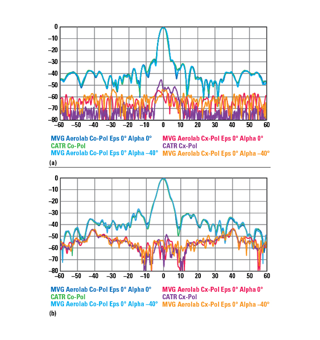
Figure 4 Comparing AeroLab and CATR co- and cross-polarization pattern measurements at ϴ = 0 and –40 degrees with ϕ = 0 degrees (a) and ϴ = 0 and –40 degrees with ϕ = 90 degrees (b).
The AeroLab introduces an innovative, multi-probe, near-field measurement technique for testing aircraft nose-mounted radomes. It provides high accuracy for testing radomes after repair and meets the RTCA-DO-213A standard requirements, enabling repair facilities to decrease the time for repairing and testing commercial aircraft nose-mounted radomes. The AeroLab provides measurement flexibility while keeping the testing footprint to a minimum, and its 3D visualization and diagnostics tool offers the repair process new insight.
MVG
Paris, France
www.mvg-world.com