
MIMO + WAVEFORMS
As mentioned, Tx orthogonality is key to the Rx channels distinguishing the Tx signals. While there are multiple ways to achieve orthogonality, almost all have costly engineering trade-offs. The choice ultimately depends on the application and the radar waveform.
Frequency modulated continuous wave (FMCW) radars are by far the most popular for automotive. Numerous FMCW MIMO implementations have been reported, with the most common using a time-division multiplexing (TDM) approach. This is not true MIMO, although it can be a good approximation, as the signals are not a snapshot of the same environment, given the time delay. Figure 4 shows how FMCW works with a three Tx radar sharing the same frequency modulated band. The radar frame is divided into three time slots, each devoted to one transmitter. The received signals are distinguished and processed based on this time division. One disadvantage of this option: since the transmitters are not operating at the same time, the maximum Tx output power is limited to the output from a single Tx. Consequently, while the FMCW TDM radar gains angular resolution, it trades maximum achievable range.
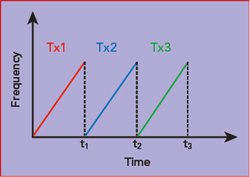
Figure 4 Frequency vs. time for an FMCW radar.
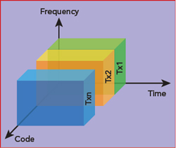
Figure 5 Code domain MIMO.
An alternative is where the transmitters share both frequency and time and are differentiated with orthogonal phase-coded waveforms (see Figure 5). Each transmitter radiates a uniquely coded signal which is “matched” by the receiver. Transmitting on all Tx channels simultaneously provides a link budget gain of 10log10 (NTx ). This can be used to increase the maximum range, without affecting other radar parameters, or to reduce the area of the silicon used for functional blocks like the power amplifiers.
Conceptually, DCM radars modulate the phase of the transmitted signal during a given time period, called the chip period or chip duration, where each phase is one of a finite number of possible phases. For simplicity, assume the modulation is binary phase shift keying (BPSK). The phase modulated signal is spread using a predefined code consisting of a sequence of chips and is mapped onto a sequence of phases to create the transmitted signal. The signal is of the form

where P is the power, fc is the carrier frequency and Φ(t) is the phase of the transmitted signal. While the phase can vary continuously to minimize bandwidth, the phase function is a sequence of phases held constant for Tc seconds, where Tc is the chip duration. That is,
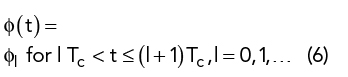
where a(t) is either +1 or −1, corresponding to Φ(t) = 0 or π, respectively.
The sequence of values of the binary modulation signal are called chips. The sequence of chips causes the spectrum of the signal to spread the energy over a bandwidth proportional to 1/Tc.
The baseband spreading waveform, a(t), that modulates the oscillator to generate the transmitted phase modulated CW signal, s(t), is given by

where a(t) is either +1 or -1, corresponding to ϕ(t) = 0 or π, respectively.
The transmitted signal from a single antenna is reflected off the targets in the environment, and the reflected signals at the receiving antenna are processed. A simple model for the received signal is
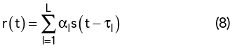
assuming L targets that reflect the transmitted signals. The transmitted signal, s(t), reflected by a target is attenuated by the factor αl and delayed by τl between the transmitter, target and the receiver. The delay between the transmitted signal and the received signal is related to the distance by dl = c τl/2, where c is the speed of light and the factor 2 reflects the roundtrip time from the transmitter to the receiver.
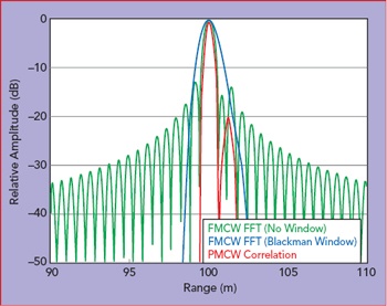
Figure 6 Correlation of two targets with large differences in radar cross section.
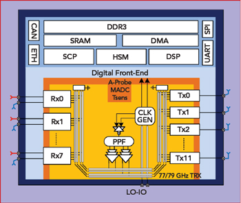
Figure 7 Radar SoC, including 77 to 79 GHz MIMO transceiver with 12 Tx and 8 x 2 Rx, DSP, memory and interfaces.
The digital signal processing includes a matched filter to determine the correlations of the received signal with various delays of the transmitted signal. In a DCM system, multiple periods of the spreading code are transmitted, and the matched filter produces an output at time t that corresponds to the correlation of the input from time t−T, where T is the duration of the matched filter’s impulse response. The red curve in Figure 6 shows the correlation between phase modulated signals that are reflected by two close targets, about 100 m distance and approximately 20 dB difference in radar cross section. The targets are easily distinguished, showing the capability of DCM systems to discriminate targets in challenging high contrast resolution scenarios. For comparison, the target discrimination of an FMCW radar are also plotted (see the green and blue curves), showing the FMCW returns limited somewhat by the windowing of the fast Fourier transform (FFT).
FIRST DIGITAL AUTO RoC
Uhnder has developed a radar sensor IC that incorporates advanced digital signal processing techniques, such as MIMO, to create a new generation of automotive radar sensors. This fully integrated radar on a chip (RoC) was designed for flexibility, a versatile platform to support diverse applications while minimizing cost.
This RoC architecture is based on DCM with phase modulation and MIMO, capable of processing up to 192 virtual receive channels without external RF PCB circuitry. The RoC (see Figure 7) integrates a 77 to 79 GHz transceiver with 12 Tx and 16 Rx channels that can be time-multiplexed to two sets of antennas, covering both azimuth and elevation profiles. The RoC uses a 15.2 to 16 GHz local oscillator (LO) generated by an external phase-locked loop, with differential LO inputs converted to quadrature using a polyphase filter.
The transmitter uses a Gaussian minimum shift keying (GMSK) digital modulator feeding a zero IF quadrature up-converter to mmWave. At baseband, a programmable pseudo-random noise (PRN) code is generated, digitally GMSK modulated and fed into current-steering 2, 4 and 8 GSPS digital-to-analog converters, whose current outputs are amplified and filtered by reconstruction filters.
Compared to BPSK implementations, this transmitter achieves higher spectral efficiency due to the absence of the large adjacent frequency sidelobes. The quadrature GMSK up-converter generates a constant envelope phase modulated signal, so it can use a fully saturated power amplifier to maximize efficiency while meeting the challenging link budget - a big challenge for all mmWave systems. Using DCM technology and MIMO enables the Uhnder design to place more power on target by simultaneously using multiple Tx channels with different codes. Transmit phased array is an available mode of operation that allows the user to trade field of view for higher effective isotropic radiated power. For a given link budget, designing smaller power amplifiers becomes a desirable and viable option.
At the receiver, the received signal is amplified with a low noise amplifier (LNA), mixed down to baseband using the same oscillator as used for the transmitter. Converted from analog to digital, the signal is digitally processed to estimate the range, frequency, Doppler and angles of the targets in the environment.
With Uhnder’s implementation, the spreading code can be a PRN sequence with a very large period, so it appears to be a nearly random sequence. The resulting signal has a bandwidth that is proportional to the rate at which the phases change (i.e., the chip rate), which is the inverse of the chip duration. By comparing the return signal with the transmitted signal, the receiver can determine the range and the velocity of reflected targets.
The Rx front-end addresses the modulated self-interference artifact from the radar’s internal transmitters, which can saturate the receiver and increase the correlation noise floor. This challenge is more significant in MIMO radars, where multiple Tx active channels may constructively sum up at specific Rx inputs. To address the self-interference artifact, the RoC cancels self-interference using a pattern generator unit combined with separate analog and digital interference cancellation units (A-ICU and D-ICU, respectively). The A-ICU runs a background channel estimation algorithm, continuously calculating the impulse response, including the signal path delays, and then applies corrections to the up-converted mmWave feedback signal, where the resulting signal is then power-combined into the transformer feeding the LNA.
The D-ICU estimates the complex sum of the wideband self-interferer presented at each receiver input and removes the residual interferer before the correlators. The radar data control unit processes up to 1024 range bins for a single radar scan. The Winograd FFT engine manages up to 800 million points per second Doppler throughput. The beamforming engine throughput is 1.6 billion beams per second and implements a covariance matrix singular value decomposition engine, which supports direction-of-arrival algorithms such as MUltiple SIgnal Classification (MUSIC), estimation of signal parameters via rotational invariance techniques (ESPRIT) and Capon’s algorithm, to further improve the angular resolution.
Compared to FMCW radars - or the newer variant fast chirp modulation (FCM) - the Uhnder architecture shifts the modulation complexity and precision to the high speed data converters and the DSP, where performance scales with the CMOS process node.
CMOS IMPLEMENTATION
The RoC was implemented in 28 nm high performance computing (HPC) CMOS technology and packaged in a fan-out wafer-level package (see Figure 8). Digital signal and other radar computational processing is supported on chip with two floating point CPUs and two DSP engines. The overall software-defined hardware pipeline is capable of over 20 TOPS baseband processing.
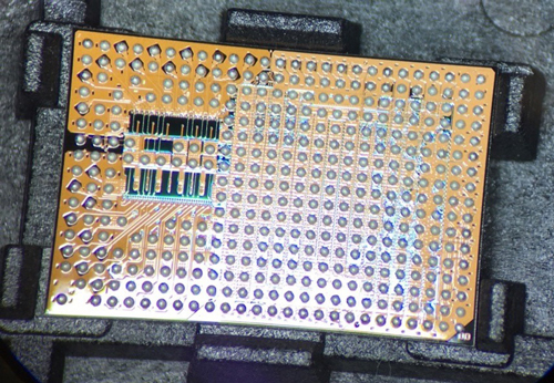
Figure 8 SoC in a fan-out wafer-level package.
At the package output reference plane, with 12 Tx active, the combined output power is approximately +19.6 dBm at 80 GHz and 125°C. The Rx noise figure measured at the analog-to-digital converter output is approximately 16 dB at 80 GHz and 125°C. Using an external PLL, the 77.5 GHz Tx phase noise at 1 MHz offset is −110 dBc/Hz. Power consumption varies with the application; typically, the RoC consumes 15 W and is biased with 0.9, 1.3 and 1.8 V supplies.
Figure 9 shows the capability of the RoC. Using the MIMO mode, Figure 9a shows a car on boresight moving at 25 mph, instantaneously detected at 290 m with 22 dB SNR. In Figure 9b, the radar, operating in phased array mode, tracks a person on boresight moving out to 280 m. Figure 9c shows the difference in angular resolution with beamforming (green line) and MUSIC processing (blue line). The targets were two −10 dBsm corner reflectors in an anechoic chamber, spaced within about ±1 degree. Figure 9d shows the improvement in the unweighted digital beamforming sidelobe performance using windowing and spatially variant apodization implemented in the hardware.
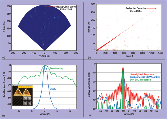
Figure 9 Radar measurements: 25 mph moving car MIMO detection at 290 m with 22 dB SNR (a), beamforming pedestrian detection to 280 m (b), −108 dBsm corner reflectors in anechoic chamber after beamforming (green) and MUSIC (blue) (c) and angle sidelobe performance after digital beamforming (red), using a Chebyshev window (blue), applying SVA in hardware (d).
SUMMARY
The Uhnder RoC is a software-defined radar, impervious to light and weather conditions and tremendously software configurable, enabling the user to choose the optimal spreading code depending on the objective of the radar system and the desired performance. By using a large number of virtual receivers, the RoC achieves best-in-class angular resolution. The results presented in this article represent just one implementation.
This RoC is the most integrated CMOS radar sensing platform to be reported.2 It represents a significant advancement in automotive radar technology and offers a path for evolution. Combining standard CMOS semiconductor technology with advanced DSP concepts from the commercial communications industry, Uhnder has introduced a new capability for automotive sensors, based on an architecture that is software-defined and customizable, to address the most demanding sensor requirements. The approach is cost-effective, scalable and open to future innovation.
References
- Massachusetts Institute of Technology, “Working Together as a ‘Virtual Telescope,’ Observatories Around the World Produce First Direct Images of a Black Hole,” ScienceDaily, April 10, 2019, www.sciencedaily.com/releases/2019/04/190410091028.htm.
- V. Giannini et al., “A 192-Virtual-Receiver 77/79GHz GMSK Code-Domain MIMO Radar System-on-Chip,” IEEE International Solid-State Circuits Conference 2019, www.uhnder.com/images/data/UHNDER_-_ISSCC_Paper.pdf.