The well known TRL calibration method eliminates measurement errors at the input and output of a device under test (DUT). It uses a matrix formalism, which is not easy to realize in experimental software. In this article, we provide the analytical version of this calculation which may be easier to implement.
Vector network analyzers (VNA) are calibrated at their own reference planes, which are generally different from the DUT reference planes. In the case of S-parameter measurements using VNAs, the DUT is measured through connecting devices, such as cables and connectors that introduce measurement errors due to phase shifts, losses and mismatches (see Figure 1). The true behavior of the DUT is obtained when these errors are removed through calibration. Various calibration methods - such as short, open, load, thru (SOLT); thru, reflect, line (TRL); and thru, reflect, match (TRM) - are used to determine the error terms. Most require accurate standards. The TRL calibration, however, does not rely on perfectly known standards.1-4

Figure 1 Calibration model comprises the DUT with input and output transitions to the VNA reference planes.
TRL CALIBRATION
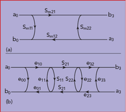
Figure 2 S-parameter flow graph for the DUT (a). The DUT with the eight-term error model (b).
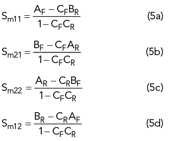
The S-parameters of the DUT are represented by the signal flow graph shown in Figure 2a. The measured S-parameters of the DUT, including measurement errors, are represented by the signal flow graph shown in Figure 2b. The S-parameters of the error terms, represented by the error boxes shown in Figure 1, are determined as follows.
In the forward direction, three ratios are measured:
In the reverse direction, three more ratios are measured:
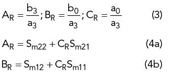
The resulting S-parameters are
CALIBRATION STEPS
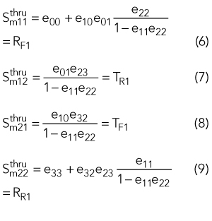
Sij are the DUT parameters and eij describe the error terms. A limited number of values for the standards must be known in advance. This is called the “calibration kit.”
The thru standard fixes the reference planes of the DUT, obtained when the DUT reference planes coincide.
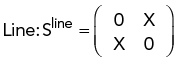
The line standard is generally an actual line with ∣X∣ close to unity, although it can be any passive reciprocal symmetrical two port.5 Then, the reference impedance corresponds to the characteristic impedance of this two port. The phase of X used in the calibration kit must be known within 90 degrees.