
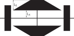
Fig. 1 Structure of the proposed T-CMRC.
A microstrip lowpass filter (LPF) is one of the vital components in a microwave communication system. Compact circuit size, low insertion loss in the passband and a wide stopband are necessary to meet modern microwave communication system requirements. Due to compact size, low cost, easy fabrication and convenient integration with other microwave circuits, planar resonators have increasingly been taken into consideration to be employed in microwave filter design. One of the techniques that can be applied in microstrip LPF synthesis is using a one-dimensional (1D) photonic band gap (PBG) structure with a microstrip transmission line. The PBG structure exhibits bandstop and slow-wave characteristics, which can be used to extend the stopband with compact circuit size. The 1D photonic band gap as a compact microstrip resonator cell (CMRC) was first introduced in 2000.1 Other types of CMRCs, such as a spiral compact microstrip resonator cell (SCMRC),2 a lowpass filter using symmetric rectangular coupled capacitors,3 a lowpass filter using tapered compact microstrip resonator cell (T-CMRC) with a non-uniform cell dimension4 and a slit-loaded tapered compact microstrip resonator cell (SLTCMRC)5 were proposed later. All of these use the photonic band gap to get a decrement number of the harmonics in the stopband with a compact size. However, in these proposed filters, the insertion loss in the passband and spurious response suppression in the stopband remain as the main challenges. To obtain wideband harmonic suppression, a defected ground structure (DGS), using slotted-ground-plane resonators, was introduced6 and a coupled-line hairpin unit was described,7 which can be a candidate for designing the LPF, instead of cascading several resonator cells. Due to the fact that the ground plane is etched, this structure does not provide mechanical robustness. Some other techniques have been proposed to synthesize microstrip lowpass filters such as an in-line beeline CMRC,8 stepped-impedance hairpin resonators,9 symmetrically loaded radial-shape patches10 and a miniaturized LPF with triangular and high-low symmetrically loaded impedance resonators.11 However, the insertion loss in the passband and a wide stopband and spurious suppression in the stopband remain as drawbacks of the proposed filters.
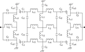
Fig. 2 L-C equivalent circuit of the proposed resonator.
In this article, a lowpass filter with an ultra wide stopband and a compact size, using a tapered compact microstrip resonator cell, is proposed. By tuning the lengths of the tapered and of the open stubs and the spacing between them, the stopband performance can be extended. The simulation of the designed structure has been accomplished using an EM-Simulator (ADS).
Filter Design
The structure of the proposed T-CMRC is shown in Figure 1. It shows that the compact microstrip resonator cell consists of two tapered cells and four vertical open stubs. The narrow connecting lines lead to the increment of series inductance. In contrast, the gap between the central narrow line and tapered cells increases the shunt capacitance, so it can give an attenuation pole in the stopband. As a result it will have an ultra wide stopband. The L-C equivalent circuit of the proposed resonator is obtained using the transmission line model shown in Figure 2, which is described as follows: L1 and L2 are the inductances of the central line; Lt1 to Lt4 are the inductances of the tapered cells; Ls1 to Ls4 are the inductances of the open stubs; Lf1 and Lf2 are the inductances of the feed line; Li1 and Li2 are inductances of the vertical line; C1 to C6 are the capacitances between tapered cells and ground; Ct1 to Ct4 are the capacitances between tapered cells and central line; C01 to C04 are the capacitances of the open stubs; and Cf is the capacitance between the feed line and the open stubs.
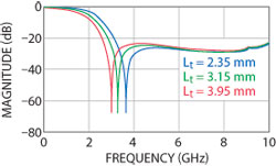
Figure 3 Simulated S-parameters of the proposed resonator as a function of Lt.
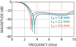
Figure 4 Simulated S-parameters of the proposed resonator as a function of L4.
The proposed resonator is implemented on a (RT/Duroid 5880) substrate, with a relative permittivity, height and loss tangent equal to 2.2, 20 mil and 0.0009, respectively. The simulated S-parameters of the proposed resonator as a function of Lt and L4 are shown in Figures 3 and 4. As shown, by decreasing Lt from 3.95 to 2.35 mm, the transmission zero will move up from the lower frequency to 2.99 GHz. When L4 increases from 1.8 to 2.6 mm, the transmission zero at 3.53 GHz will approach the lower frequency. The transmission zero can be controlled by increment and decrement of the parallel capacitance and series inductance. The reason that the transmission zero approaches the lower frequency is that the increase in series inductance leads to a decrease in the resonant frequency of the equivalent LC circuit. The tapered cells are used to control the transmission zeros and the cutoff frequency. By optimizing the tapered cells’ dimensions, the cutoff frequency can be reduced. The open stubs are used to provide the additional capacitance and inductance to control the harmonics and spurious suppression.
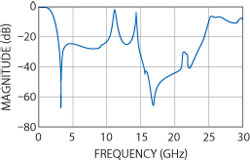
Fig. 5 S-parameter of the proposed resonator.
In order to achieve ultra wide stopband, the open stubs need to be optimized. The S-parameter simulation of the proposed resonator is illustrated in Figure 5. It can be seen that its insertion loss from DC to 1.33 GHz is less than 1 dB. The |S21| is −20 dB at 2.82 GHz. The proposed structure has a transmission zero at 3.26 GHz, with −67.87 dB in the stopband near the passband.
Simulation and Measurement
To obtain a filter with an ultra wide stopband, two resonators with the same dimensions are used. For more attenuation of the harmonics in the stopband, the open stubs and delta stubs are vertically connected to the central microstrip line. If the stopband is divided into two parts, namely the lower frequencies part and higher frequencies part, the open stubs will be used to control harmonics and spurious suppression at lower frequencies and harmonics at higher frequencies are suppressed using the delta stubs.
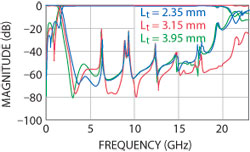
Figure 6 Simulated S-parameter of the proposed filter as a function of Lt.
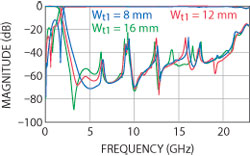
Figure 7 Simulated S-parameters of the proposed filter as a function of Wt1.
An EM-Simulator (ADS) was used to optimize the resonator dimensions in order to obtain the LPF with the desired characteristics. As shown in Figure 6, by increasing Lt from 2.35 to 3.95 mm, the transmission zero at 3.7 GHz has been moved to a lower frequency. A similar case has happened in Figure 7, in which Wt1 was increased from 8 to 16 mm. Therefore, the transmission zero in the stopband can be easily controlled with the dimensions of the proposed resonator. The dimensions of the obtained LPF shown in Figure 8 are as follows: Wt1 = 15.07 mm, Wt2 = 4.08 mm, Lt = 3.15 mm, Ws1 = 5.07 mm, Ws2 = 1.6 mm, Ls2 = 3 mm, L1 = 2.94 mm, L2 = 10.95 mm, L3 = 15.9 mm, L4 = 2.2 mm, L5 =1.5 mm, W1 = 0.2 mm, W2 = 0.3 mm, W3 = 0.45 mm, Lf = 1.5 mm, Wf =1.5 mm, Ls1 = 2 mm and Ws = 7.9 mm.

Figure 8 Structure of the proposed filter.
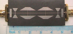
Figure 9 Photograph of the fabricated filter.
The proposed LPF, using the obtained T-CMRC structure with the above dimensions, has been fabricated with a microelectronic technology in accordance with the pattern shown previously. A photograph of the fabricated filter is shown in Figure 9. The measurements of the proposed LPF are carried out using an Agilent network analyzer N5230A. Figure 10 shows the simulated and measured S-parameters of the lowpass filter using the proposed structure, where |S11| and |S21| are in dB. As can be seen, the transition band is from 1.58 to 1.97 GHz with −3.25 to −20.25 dB, respectively. Significantly, two transmissions zero at 3.3 and 5.6 GHz with −76.33 and −59.86 dB will contribute to create a sharper transition from the passband to the stopband. The insertion loss in the passband is less than 0.1 dB from DC to 1.15 GHz, which is 73.25 percent of the passband. The return loss is better than 20 dB, which means a good impedance match to the I/O. The return loss in the stopband region is close to 0 dB.
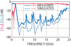
Fig. 10 Simulated and measured S-parameters of the lowpass filter.
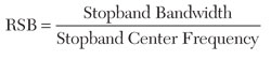
By optimizing the open stubs, delta stubs and tapered dimensions, the harmonics in the stopband are more attenuated and the stopband is observed from 1.97 to 22.3 GHz with better than 20 dB, which is approximately 167.6 percent bandwidth; therefore, the designed filter has an ultra wide stopband. The relative stopband bandwidth (RSB) is defined as:
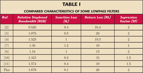
It is also interesting to notice that the T-CMRC lowpass filter has a 167.6 percent stopband, with larger and better performance than the filters cited in the references, as shown in Table 1. In the table, the suppression factor (SF) is based on the stopband suppression. For example, if the stopband suppression is less than −15 dB, then SF is considered as 1.5. Based on the results, it can be claimed that the T-CMRC filter has at least two advantages over the conventional tapered structure: (i) wider stopband and (ii) flat response in the passband. The proposed structure, compared with the conventional tapered compact microstrip resonator cell,4 has a 25.38 percent reduction in size and 17.72 percent increase in bandwidth. The skirt performance is improved, so the transition band has 13.3 percent decrements. The stopband is from 1.97 to 22.3 GHz, and has 44.66 percent increase. The size of this filter is 51.98 × 11 mm.
Conclusion
In this article, a lowpass filter, based on an enhanced microstrip resonator using a tapered compact microstrip resonator cell, is presented. The lowpass filter has the characteristics of a low insertion loss, an ultra wide stopband and a high return loss. A compact ultra wide stopband lowpass filter is designed by connecting two of the proposed T-CMRC in series. Tapered cells, open stubs and delta stubs, which are coupled to the main line, allow the designer to control the stopband location and reduce the number of harmonics. The designed filter has a 25.38 percent reduction in size, a 17.72 percent increase in bandwidth and the stopband is from 1.97 to 22.3 GHz with a 44.66 percent increase in the stopband compared to the conventional tapered compact microstrip resonator cell. With all these features, the proposed filter is applicable for modern communication systems.
References
- Q. Xue, K.M. Shum and C.H. Chan, “Novel 1-D Microstrip PBG Cells,” IEEE Microwave and Guided Wave Letters, Vol. 10, No. 10, October 2000, pp. 403-405.\
- J. Gu and X. Sun, “Compact Lowpass Filter Using Spiral Compact Microstrip Resonator Cells,” Electronics Letters, Vo1. 41, No. 19, September 2005, pp. 1063-1065.
- L. Li and Z.F. Li, “Compact Quasi-Elliptic Lowpass Filter Using Symmetric Rectangular Coupled Capacitors,” Electronics Letters, Vol. 44, No. 2, January 2008, pp. 124-125.
- L. Li, Z.F. Li and Q.F. Wei, “Compact and Selective Lowpass Filter with Very Wide Stopband Using Tapered Compact Microstrip Resonator Cells,” Electronics Letters, Vol. 45, No. 5, February 2009, pp. 267-268.
- M. Hayati and A. Lotfi, “Elliptic-Function Lowpass Filter with Sharp Cutoff Frequency Using Slit-Loaded Tapered Compact Microstrip Resonator Cell,” Electronics Letters, Vol. 46, No. 2, January 2010, pp. 143-144.
- C.J. Wang and C.H. Lin, “Compact Lowpass Filter with Sharp Transition Knee by Utilizing a Quasi-π-Slot Resonator and Open Stubs,” IET Microwave and Antennas Propagation, Vol. 4, No. 4, April 2010, pp. 512-517.
- F. Wei, L. Chen, X.W. Shi, Q.L. Huang and X.H. Wang, “Compact Lowpass Filter with Wide Stopband Using Coupled-Line Hairpin Unit,” Electronics Letters, Vol. 46, No. 1, January 2010, pp. 88-90.
- F. Zhang, J.Z. Gu, C.Y. Gu, L.N. Shi, C.F. Li and X.W. Sun, “Lowpass Filter with In-Line Beeline CMRC,” Electronics Letters, Vol. 42, No. 8, April 2006, pp. 472-474.
- L.H. Hsieh and K.C. Chang, “Compact Elliptic-Function Lowpass Filters Using Microstrip Stepped-Impedance Hairpin Resonators,” IEEE Transactions on Microwave Theory and Techniques, Vol. 51, No. 1, Part 1, January 2003, pp. 193-199.
- J. Wang, L.J. Xu, S. Zhao, Y.X. Guo and W. Wu, “Compact Quasi-Elliptic Microstrip Lowpass Filter with Wide Stopband,” Electronics Letters, Vol. 46, No. 20, September 2010, pp. 1384-1385.
- J.P. Wang, L. Ge, Y.X. Guo and W. Wu, “Miniaturized Microstrip Lowpass Filter with Broad Stopband and Sharp Roll-off,” Electronics Letters, Vol. 46, No. 8, April 2010, pp. 573-575.
Yasin Yousefzadeh received his bachelor’s degree in Communication Engineering from Azad University, Urmia, Iran, in 2008, and his master’s degree in Electronics Engineering from Razi University, Kermanshah, Iran, in 2011. He is now with the Computational Intelligence Research Center, Faculty of Engineering, Razi University. His current research interests include microwave and millimeter-wave devices, circuits and systems.
Mohsen Hayati received his bachelor’s degree in Electronics and Communication Engineering from Nagarjuna University, India, in 1985, and his master’s and doctorate degrees in Electronics Engineering from Delhi University, Delhi, India, in 1987 and 1992, respectively. He joined the Electrical Engineering Department, Razi University, Kermanshah, Iran, as an Assistant Professor, in 1993. At present, he is an associate professor in the Electrical Engineering Department, Razi University. His current research interests include application of computational intelligence, artificial neural networks, fuzzy system, neuro-fuzzy systems and electronic circuit synthesis, modeling and simulations, microwave and millimeter-wave devices, circuits, and systems.