

For active antenna arrays, a significant amount of production test time is spent on calibration. Large arrays can consist of hundreds or thousands of elements and it is necessary to characterize the phase and gain alignment between these elements to ensure precise beam-forming. In addition, the test time to align these elements can increase dramatically as the number of elements increases. Hence, the ability to accelerate test by using multiple coherent measurement channels is a significant benefit.
Today, a multi-port, network analyzer is typically used to make relative gain and phase measurements on the antenna. The measurements are generally made serially across all of the antenna ports, or channels, using a switch matrix. This can result in significant test times, especially for large arrays consisting of hundreds or thousands of elements.
Reducing the test time to calibrate phased array antennas can be accomplished in several ways. The method that provides the greatest reduction in test time must exploit the test range capabilities and the specific antenna architecture it is used with. Fundamentally, measurements of relative magnitude (gain) and phase are required for the relative alignment of elements in the antenna, but these tests need to be conducted over a variety of frequency and phase AUT states using RF/uW probe(s) in the test range.
In order to address the challenges of calibrating large, multi-channel antennas, Keysight has developed a reference solution shown in figure 1. This reference solution is a combination of hardware, software, and measurement expertise providing the essential components of a narrow-band antenna calibration test system.
The M9703A was selected for the system and is uniquely suited to this application due to the real-time DDC capability and wide BW. It also has excellent channel-to-channel phase-coherence across multiple modules. While the reference solution is targeted at narrowband measurements, the M9703A can be used with wider bandwidth signals (up to 300 MHz with DDC and 600 MHz without DDC). Given the RF/uW frequencies used in many phased array antennas and that we are using an IF digitizer, it is necessary to use analog mixing to downconvert to an IF within the passband of the M9703A. This is accomplished using PXI-based, 4-channel down-converters. Signal conditioning is also provided in the PXI form-factor to match the down-converter output to the input of the digitizer.
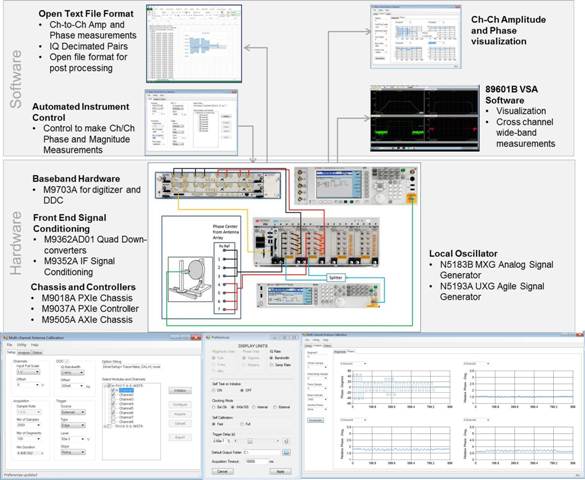
Figure 1– Keysight’s Modular MAC Reference Solution
The Keysight multi-channel calibration reference solution includes software which was specifically designed for this application. It is made up of two parts: 1) evaluation GUI and 2) .NET Class Library. The key software component in the reference solution is a .NET class library (.NET *.dll). In specific, the class library is named MODIQController.dll. The reference solution GUI provides a tool for demo and evaluation of this digitizer-based solution. It provides the functions such as digitizer setup and control, visualization of cross-channel results, and measurement interval analysis.
The .NET class library (figure 2) provides all cross-channel measurements, digitizer control (via 64bit IVI-COM driver), and waveform data structures and resides within the MODIQController.dll. This class library automates collection of measurements on one or more M9703A digitizers in a multi-module synchronous set. It uses digital downconversion (I&Q samples) and optionally segmented (multi-record) memory. It also provides methods to extract single channel and cross-channel phase and gain measurements.
Source code is provided with the reference solution so that the antenna test engineer can use as is or enhance to fit a specific application. This class library can be readily re-used in any .NET programming language or other programming languages that support calling .NET assemblies.
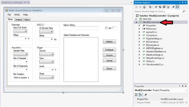
Figure 2 –MAC Reference Solution .NET MODIQController.dll
The primary advantage to using the reference solution described here is the ability to make measurements across many coherent channels concurrently. This parallel approach can provide substantial increases in calibration throughput if it is supported by the antenna architecture and/or test range (Rx/Tx). Furthermore, the use of fast frequency switching sources in this reference solution can provide addition throughput improvements given that the antenna can settle quickly enough as the stimulus steps to the various tones used in the calibration.
Below you will see an example of a fast data acquisition operation resulting in 6.7 million cross-channel measurements (48 intervals * 20e3 records * 7 ratio measurement channel pairs). With an RF signal at 3.3GHz center frequency, the down-converted 300MHz IF is sampled by the M9703A digitizer to produce a relative phase measurement variance of 0.008 degrees^2. Each measurement is made by integrating multiple I&Q samples over the measurement interval. Groupings of the measurements made at different AUT states are then collected into segments of memory in the digitizer (multi-record or segmented memory feature). Finally, the data is uploaded from the digitizer to the PC controller at the conclusion of the complete measurement cycle (including all segments).
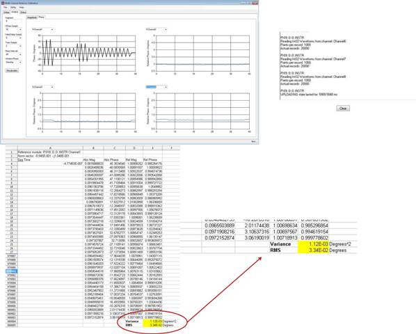
Figure 3 - 1K samples, 20K records, 8 ch (Setup 1)
An important consideration for such a measurement system is the large amount of data that will need to be uploaded from the digitizer to the PC. With the fast PCIe Gen2 x8 link in this modular system, we can achieve up to 1GB/sec data transfer rates (in examples shown here we achieved >200MB/s (setup 1 shown in 3) and >400MB/s (setup 2 shown in figure 4), depending on setup parameters like number of segments, number of samples, etc). Because the software used in the reference solution was designed in .NET 4.5 (C#, Visual Studio 2012) and compiled for x64 OS (such as Windows 7 or 8 64bit), very large amounts of memory can be allocated in the memory collections of the application. This enables uploading up to 2GB per channel acquisitions to a controller with sufficiently large memory.
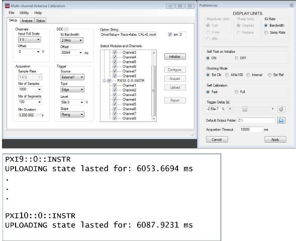
Figure 4- 20K samples, 2K records, 16 ch (setup 2) => 5.12GB data transfer in 12.14 seconds
While testing fast is often associated with lower resolution measurements, using the M9703A digitizer as the measurement core of an antenna array test reference solution enables increased test throughput with optimized sensitivity and resolution. The phase coherent, multichannel M9703A digitizer enables increased production capacity by performing multiple measurements in parallel. The Keysight Multi-Channel Antenna Calibration reference solution is built upon the M9703A and is a modular and flexible solution. It can easily be scaled to accommodate additional antennas in the array under test. The reference solution provides software specially designed to make cross-channel amplitude and phase measurements and the software can be modified to meet application-specific requirements.
For more information, go to: www.keysight.com/find/axie-antennatest