

Rotary joints based on rigid waveguide can provide high-performance, dependable connections in many commercial and military RF/microwave systems. But matching the right waveguide rotary joint to a particular application can call for a bit of “rotary joint know-how” beyond simply selecting proper waveguide sizes. These are precision components that can help keep high-frequency signals connected under a variety of conditions, and are available in different waveguide sizes as well as compact, coaxial versions as needed.
Rotary joints, whether waveguide or coaxial types, allow the connection of high-frequency analog and high-speed digital signals in setups where at least one of the transmission lines must rotate, such as when connected to an antenna. Ideally, a rotary joint provides an electrical connection that remains consistent over time and with movement of the joint, with low insertion loss and with power-handling capabilities that exceed the maximum limits of the system. Rotary joints in both waveguide and coaxial forms have been used in many different types of high-frequency systems, including in air-traffic-control (ATC), radar, satellite-communications (satcom), and surveillance systems.
 Comparing and Specifying Rotary Joints
Specifying a rigid waveguide rotary joint or other waveguide component usually starts with a required frequency range. For a rigid rectangular waveguide (WR) component, the frequency range is indicated by the WR waveguide size, such as a WR28 rotary joint with a frequency range of 26.5 to 40.0 GHz or a WR75 rotary joint, with a frequency range of 10.0 to 15.0 GHz. Lower WR numbers indicate smaller rigid waveguide dimensions and higher operating frequencies for the waveguide components.
A rotary joint will also have a power rating associated with it, whether the rotary joint is maintained in dry air or in nitrogen or other controlled atmosphere. High-power applications, such as transmitters, may require excellent power-handling capabilities, and these can be compared for different waveguide rotary joints in terms of continuous-wave (CW) power or peak power levels. When comparing peak power levels for different joints, the measured power should refer to test signals for the same pulse length. The power-handling capabilities of a waveguide rotary joint are tied to its composite materials, which are typically copper, brass, or aluminum, and with silver-plated or painted finishes; these construction materials, including additional mounting flanges and terminations, also impact the weight of a rigid waveguide rotary joint for a given WR size as well as its insertion-loss performance.
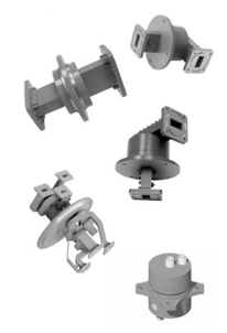
Waveguide rotary joints are typically produced in a number of different mechanical configurations in support of different transmission-line interconnections in both single-channel and multiple-channel applications, for use with analog, digital, or even fiber-optic signals. Some configurations may even combine waveguide and coaxial transmission lines within the same rotary joint for efficiency. Examples of different waveguide rotary joint mechanical configurations include I, L, U, and F formats, with one arm of the rotary joint fixed to a system housing or enclosure and the other arm free to rotate. In an I style rotary joint, for example, two transmission arms are in line, while in an L style rotary joint, one of the transmission arms is at a right angle to the other transmission arm. In an F style rotary joint, an in-line transmission arm is fixed to the housing, while one right-angle transmission arm is free to rotate. In a U style rotary joint, two transmission arms are at right angles to the center of rotation, with one fixed to the housing or enclosure and one free to rotate.
Rotary joints can be characterized and compared in terms of how well they rotate, such as their electrical performance with rotation, their maximum rotational speeds, and even their operating lifetimes, which are usually indicated as an expected number of rotations for the rotary joint. Rotary joints are rated for maximum rotational speeds, such as 500 rpm, and the operating lifetime—usually expressed as the total number of expected rotations—assumes operating a rotary joint within its rated speed limits. The operating lifetime of a rotary joint depends upon a number of other factors, including mechanical loading, input power levels, and operating temperatures.
The electrical performance of a rotary joint can change with its rotation, and such parameters as insertion loss, phase, and voltage standing wave ratio (VSWR) are typically characterized dynamically as a function of rotation and documented as phase WOW, or insertion loss WOW, or VSWR WOW. This is typically a ratio of the maximum to minimum deviations of a performance parameter with rotation, such as
VSWR WOW = (maximum VSWR)/(minimum VSWR) for the effects of rotary joint rotation on VSWR.
Waveguide rotary joints can be compared in terms of many fundamental performance specifications, such as insertion loss and VSWR with frequency, in addition to some parameters that are somewhat unique to waveguide rotary joints, such as leak rate and torque. Most rotary joints are equipped with seals to allow pressurization, and are tested for leak rate, for use in different environments. The leak rate provides an estimation of a component’s expected behavior in a controlled environment, such as a nitrogen environment. The torque specification for a rotary joint is a measure of the mechanical resistance during startup or turning of the joint, usually in Newton-meters (Nm). It provides a means of comparing the different levels of force needed for working with different rotary joints in a given application.
Of course, the use of transmission-line transitions, such as a coaxial-to-waveguide transition, enables the incorporation of different types of transmission lines within a single-channel or multiple-channel rotary joint. Whereas waveguide rotary joints are interconnected according to their frequencies and waveguide sizes, coaxial rotary joints are capable of broader potential frequency bandwidths and interconnections according to broadband coaxial connectors, such as Type N, TNC, and even SMA connectors with bandwidths as wide as DC to 40 GHz. Coaxial rotary joints are often employed for combination functions within RF/microwave systems, including as couplers and rotary joints.
As developers of waveguide and coaxial rotary joints, we typically provide standard models of both types of rotary joints and can detail some of the performance differences, in terms of insertion loss, VSWR, and power-handling capabilities, between the two types of rotary joints. And in some cases, the different transmission-line types can be combined within a single rotary-joint solution that provides both waveguide and coaxial interconnections. In most cases, these are unique RF/microwave components that perform unique roles in high-frequency systems.
Contact MDL for your Rotary Joint questions or requirements at 1-781-292-6684 or visit our website at www.mdllab.com.