

Simon Mathias is the vice president of sales and marketing for Tektronix partner Mesuro Ltd. Simon has spent over 20 years of his career in the test and measurement industry.
After posting the first blog, I realized we probably jumped in at the deep end going straight into one of the more complex technical challenges facing power amplifier engineers today. Therefore, I thought it might be worthwhile to take a step back and look at the various types of load pull system available and some of their benefits and pitfalls.
There are fundamentally, sorry no pun intended, four main types of load pull system and we will cover these below, with all systems, in one shape or form able to offer harmonic load pull capability to a greater or lesser extent.
Passive Tuning
A traditional passive mechanical tuner system operates by inserting a probe (commonly referred to as a tuning slug) into the airline at some variable depth. The further the probe penetrates into the airline, the greater the magnitude of reflection. By sliding the probe along the length of the airline, the phase can also be varied. Therefore, it is possible to present an impedance on the Smith Chart to the DUT by selecting the appropriate vertical and horizontal positions of the probe.
Fundamental load-pull tuning is achieved with a single tuning probe, or a combination of tuning probes based on the fundamental frequency impedance. Harmonic load-pull tuning is achieved using a combination of two, three, or more probes in cascaded or filtered configurations.
One disadvantage is there a finite limit in the GL that can be presented, as any loss between the DUT and the tuner reduces the maximum reflection that can be presented. Also if a fundamental only configuration is adopted and unknown out of band impedances are presented to the DUT, stability issues can result for some devices. While mechanical tuners are simple, less expensive and can handle high power, there is no physical way to overcome the losses involved with the system, limiting the achievable GL.
Active Closed Loop
The active closed loop methodology uses an phase shifted, amplified version of b2 as the reflected signal a2. To accomplish this, a coupler or circulator is used to direct the signal (b2) from the DUT through a variable amplification stage, with control of both magnitude and phase, and then re-injecting the signal as a2 back into the device. The figure belowshows the basic block diagram for a typical closed-loop fundamental tuning system.
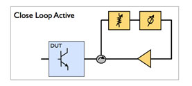 There are several advantages to this technique over traditional mechanical load- pull tuners including speed, control of gamma to the edge of the Smith chart and beyond, and ease of integration especially in on-wafer measurement systems. Since the system relies on electrical tuning with no moving mechanical parts, tuning can be fast. The amplifier within the closed-loop configuration can be used to increase a2 so that GL can approach unity at the DUT’s reference plane.
On the negative side, oscillations can occur in an active closed-loop load-pull system due to leakage from passive components. Significant filtering can be employed to reduce the chance of this occurring, but this typically makes the system approach narrow band. Also, the use of high-power linear amplifiers in the active closed-loop load-pull approach can add considerably to the cost of the system.
Active Open Loop
Open-loop active load pull relies on external signal sources to inject a signal into the output of the DUT, thereby creating a2. The simple active tuning chain consists of the signal source, a variable phase shifter, and a variable gain stage, which are normally integrated within commercially available signal generators. With active load-pull techniques, harmonic load-pull tuning is simplified since a multiplexer can be used to merge multiple active tuning paths, one per frequency. Any losses inherent within the multiplexers or other parts of the measurement network are easily overcome by the amplifiers used within the active tuning chain.

Unlike the closed-loop system, these amplifiers do not have to be linear since the user specified reflection coefficient is reached using an iterative step process within the control software. The benefits of active open-loop systems are similar to those of closed-loop systems: fast tuning, high-gamma tuning, and ease of integration with on-wafer measurement systems. As the name suggests, open-loop systems have another advantage over closed-loop systems: there is no feedback path and therefore no chance of tuning- loop oscillation.
Disadvantages center on speed and cost. Since iterations are required to set the desired reflection coefficient, measurement speed can be an issue. The cost of system amplifiers is another hurdle, although this can usually be overcome through the use of broad-band impedance transformers. Overall, open-loop active load pull systems tune quickly, are capable of GL >= 1, and can offer ease of integration.
Hybrid Load Pull
The hybrid load-pull system offers the advantages of passive and active load-pull approaches while having the potential to minimize the disadvantages of both. Hybrid load pull refers to a combination of active and passive tuning within the same system.
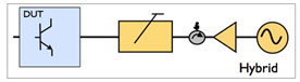
Traditional passive mechanical tuners can be used to reflect high power at the fundamental frequency allowing a much smaller active injection signal, using much smaller amplifiers, to overcome the system losses and achieve GL = 1.
Since the power levels of harmonic frequencies are often well below the power of the fundamental signal, lower power amplifiers can be used with active tuning to accomplish active harmonic load pull. Both cases require only low power levels for active tuning. One thing to remember is that such systems typically have the same problems of uncontrolled out of band impedance presenting potential stability issues.
Passive, Hybrid or Active, which method to use?
Ultimately that depends upon what you are trying to achieve. As you can see each approach has its positive and negative points. With the desire to push the efficiency boundaries than harmonic tuning, would appear, to have a greater role to play in device characterization and test.
Let’s hear your thoughts on which methods you are employing and why you see benefit in either sticking with it, or the potential to try alternative approaches.