
The company’s initial offering is two distinct product families. First, the R&S RTM family targets the broadest segment of the oscilloscope market with specifications that include up to 500 MHz of test bandwidth, 5 Gsample per second acquisition rates, and memory depths of up to 8 Msample. The second is the R&S RTO family that targets the most challenging high-performance test and measurement applications. Two and four-channel models are available with measurement bandwidths of 1 GHz and 2 GHz and a maximum per channel sampling rate of 10 Gsample per second.
THE R&S RTM
Positioned as universal oscilloscopes that satisfy the requirements of the vast majority of product development engineers, researchers and service technicians, the R&S RTM family has an intuitive interface that includes color-coded control elements, flat menu structures and a brilliant 8.4-inch XGA TFT color display. They are also among the smallest and lightest instruments in their class. Figure 1 shows the RTM 1054.
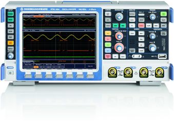
Fig 1. The R&S RTM 1054 is for everyday use.
The engineers who designed the family emphasized accurate signal display, excellent time resolution – even for long sequences – and signal analysis tools that combine speed with ease of use. Available in two and four-channel models, the oscilloscopes provide maximum input sensitivity of 1 mV/div without bandwidth limitations or software-based zooming. This level of test performance is achieved through extremely low-noise front-ends and a low-noise A/D converter.
Analysis tools include a QuickMeas function that displays values for a currently active signal at the push of a button, which is illustrated in Figure 2. Values available through QuickMeas include positive and negative peak voltage, rise and fall time and mean voltage. Troubleshooting is quicker and easier thanks to functions such as flexible zoom, push-button FFT, and a large number of cursor-based measurements.
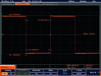
Fig 2. The QuickMeas function displays values for a currently active signal at the push of a button
A wide range of triggering options is available. In addition to edge and video trigger modes, the oscilloscopes have logical and pulse-width triggers. The latter identifies signal pulses that deviate from the norm. The B trigger allows either time-delayed or event-delayed sequence triggering. Individual buttons on the front panel allow fast access to frequently used functions. Users only need to push the Trigger Level button, for example, to set the instrument to 50 percent of the signal amplitude.
To speed up error detection, three options are available for highlighting rare events: Persistence mode superimposes multiple waveforms so that sporadic signals stand out; the inverse brightness display mode reverses the instrument's natural tendency to make display points that are otherwise constantly overwritten bright; and the temperature color gradient mode color-codes the frequency distribution of display points according to the temperature color scale.
In addition, users can choose from three display modes depending on their test requirements. The X-Y (-Z) mode is ideal for analyzing frequency and phase relationships between two signals. The intensity of the X-Y curve can be modulated by the amplitude variations of another signal (Z). When the Z signal is active, a preview window shows the Z signal versus time.
The ‘Acquisition’ menu lets users choose between different decimation modes (Sample, PeakDetect, and HighRes) and waveform arithmetic (Envelope, Average, and Smooth) and combines them. The new ‘Smooth’ mode displays a sliding average that suppresses higher frequency components – even for non-periodic signals.
THE R&S RTO
The R&S RTO family includes the model R&S RTO1024, which is shown in Figure 3. The entire family takes measurement precision and error detection to a new level. Conventional oscilloscopes, for example, capture signals at best during 0.5 percent of the acquisition cycle. This new family raises that figure at least 20-fold, which can greatly reduce the time required to identify signal anomalies created by design bugs.

Fig 3.The R&S RTO 1024
The technology innovations responsible for this and other performance advances include an ASIC that processes data at an unprecedented rate, the industry's first purely digital trigger architecture, and a single-core A/D converter that delivers very high dynamic range.
Thanks to an ASIC that was designed in-house the R&S RTO family is able to process many signals in parallel, making it capable of analyzing one million waveforms per second.
Conventional digital oscilloscopes operating at their maximum sampling rate spend most of their time processing data. Even the best are ‘blind’ a minimum 99.5 percent of the time, which means that signal faults can remain hidden to the user. The new oscilloscopes sample the signal more than 20 times more often, which in the final analysis significantly reduces debugging time. Despite this high acquisition rate, all settings and analysis functions remain available without reducing the measurement speed.
The processing ASIC also contains hardware support for measurement and analysis functions, such as spectrum display, mathematical operations, cursor measurements, histograms and mask tests. Figure 4 shows a high-speed mask test with the R&S RTO. Even during complex signal analysis, the ASIC's high degree of parallel processing ensures a high acquisition rate. For example, the acquisition rate during a mask test remains at a very high level (more than 600,000 waveforms/s).

Fig 4. High-speed mask test with R&S RTO: Within ten seconds more than six million waveforms are acquired, evaluated and displayed.
Fast Fourier Transform (FFT) is very fast, with the high acquisition rate conveying the impression of a live spectrum on the screen. Combined with the persistence mode, even rarely occurring events in the spectrum can be observed. Also, the purely digital trigger architecture avoids the pitfalls of analog trigger systems in two ways. First, it allows the trigger and the captured data to share a common signal path and a common time base. The result is exceptionally low trigger jitter and exact assignment of the trigger to the signal.
The single-core A/D converter running at 10 Gsample per second adds more measurement accuracy. Compared to the conventional approach of using several A/D converters operating in parallel with time offset, the single-core, 8-bit converter with more than seven effective bits achieves very high dynamic range. The result is minimal signal distortion and low inherent noise. Figure 5 shows typical inherent noise: standard deviation (S-dev) with histogram measurement.

Fig 5. Typical inherent noise: standard deviation (S-dev) with histogram measurement. Measurement conditions: 50 mV/div, resolution 100 ps, no filter.
R&S RTO oscilloscopes also offer superior access to waveforms in memory (standard size 20 Msample). Measurement data stored in memory is always immediately available for analysis regardless of the function being performed with the measurement ended. A time stamp for the waveform clearly identifies when the events took place. Depending on the memory option, extensive data for effective debugging is also available to the user.
Despite the wide variety of measurement and analysis functions, the new oscilloscopes are easy and intuitive to operate. The user-friendly screen design with semi-transparent dialog boxes, signal icons to preview waveforms in real time and a configurable toolbar lets users perform even complex measurement and analysis tasks quickly. The handy, compact instrument comes with a 10.4 inch touch screen.
The straightforward menus at the bottom of the screen make it possible to reach any of the settings with no more than two clicks. The flat menu structures and crosslinks to logically associated settings simplify navigation. Signal flow diagrams in the dialog boxes visualize the progress of signal processing, and the toolbar at the top of the screen offers fast access to frequently used functions, such as Zoom, multi-level Undo/Redo, Histogram, and FFT.
High-Quality Probes
Active and passive probes are the ideal complement to oscilloscopes. Two innovations have been introduced for the active probes. The configurable micro button allows engineers to control the oscilloscope directly from the probe as shown in Figure 6. The R&S ProbeMeter delivers precise DC voltage measurements for quickly checking supply voltages or operating points, regardless of base unit’s channel settings.
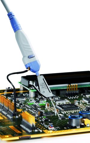
Fig 6. The configurable micro button allows engineers to control the oscilloscope directly from the probe
THE FULL SPECTRUM
With these two new families of oscilloscopes Rohde & Schwarz has begun to establish itself in the marketplace. They are set to become a benchmark in the high-performance and midrange segment and although not part of the most recent announcement, the company also has the basic end of the oscilloscope market covered through its Hameg Instruments subsidiary, which designs and markets oscilloscopes with frequency ranges of up to 350 MHz.