
RF and microwave microstrip BPFs with high selectivity, low insertion loss, suppression of spurious sideband and wide stopband are widely used in recent wireless communication systems.1 In 2002, the IEEE extended the 802.11b standard in the 2.4 to 2.4835 GHz frequency range; the fast development of WLAN communications has also made high performance essential for RF BPFs.2 However, many microstrip planar BPFs have spurious resonant frequencies, which may be close to the operating frequencies, with severe influence on the system.3 Although quarter-wavelength resonator filters have their first spurious passband at 3ƒ0, where ƒ0 is the center frequency, they require short circuit connections with via holes, which creates a parasitic effect difficult to cancel.4 BPFs using low temperature co-fired ceramic and stepped impedance resonators are able to control the spurious responses, but they can only be implemented in certain filtering configurations with high insertion loss.5,6 The open loop resonator filter has a pair of attenuation poles at finite frequencies, making it a viable intermediate between the Chebyshev and elliptic-function filters.7,8 Defected ground structures (DGS) have been applied to improve the spurious response of the microstrip open loop resonator BPF; it also results in some problems such as high insertion loss and electromagnetic compatibility interference.9

Figure 1 Configuration of conventional asymmetric spurlines.
In this article, a 0° feed open loop resonator WLAN BPF is presented, using a spurline and quarter-wavelength open-circuited stubs to improve the out of band response. The use of the spurline and quarter-wavelength open-circuited stubs realizes a wide range of spurious response suppression without changing the passband performance. By modifying the dimensions of spurline and quarter-wavelength open-circuited stubs, different stopband frequencies are obtained. The proposed 0° feed open loop resonator BPF shows stopband attenuation losses better than 20 dB from 2.6 to 10 GHz and insertion loss as low as 1.05 dB. This BPF is characterized by two attenuation poles, low insertion loss and high out of band rejection.
Figure 2 Frequency response of the conventional asymmetric spurlines.
Spurline and Quarter-Wavelength Open-Circuited Resonators
Figure 1 shows the configuration of conventional asymmetric spurlines, which are etched on the microstrip transmission line.10,11 This is different from the DGS, which is located on the ground side. The spurline is etched as an inverted "L" shape slot on the microstrip transmission line. Generally, the spurline dimension parameters include slot width s, slot length l and slot height h, where the slot gap provides a capacitive effect while the narrow microstrip line exhibits an inductive effect.12,13

Figure 3 The proposed resonator.
The spurlines are etched on a microstrip line with a width of w = 2.73 mm, which corresponds to a 50 Ω characteristic impedance. The substrate has a relative dielectric constant of 2.65 and a thickness of 1 mm for simulation. The transmission characteristics of the spurlines are simulated using the electromagnetic simulator IE3D. Figure 2 shows the transmission characteristics of the asymmetric spurlines for various l2. The other dimensions include: s = 0.2 mm, l1 = 12 mm, h = 0.6 mm and w = 2.73 mm. When l2 is increased from 6 to 8 mm, the resonant frequency shifts to a lower range, from 8.56 to 6.52 GHz. It is also found that the resonant frequency caused by l1 changes slightly at 4.3 GHz. It is concluded that the asymmetrical spurlines provide obvious dual-band gap characteristics, with two resonant frequencies, and the resonant frequencies can be controlled by adjusting the length of l1 and l2.

Figure 4 Stopband characteristics of the proposed resonator.
Figure 3 shows the layout of the proposed resonator, which consists of theasymmetric spurlines and two quarter-wavelength open-circuited stubs using a folded shape for compact size. As is known, a quarter-wavelength open-circuited stub has a bandstop property at a finite frequency range, similar to a single spurline. The proposed resonator structure can generate a wide stopband with four attenuation poles by modifying the dimension parameters li, for i = 1, 2, 3, 4. As shown in Figure 4, the resonator has a wide stopband from 5.13 to 8.25 GHz with a return loss lower than 13 dB and has little effect at the low frequency range. The dimensions include: d = 3 mm, s = 0.2 mm, c = 1 mm, h = 1 mm, w = 2.73 mm, l1 = 8 mm, l2 = 7 mm, l3 = 5.8 mm and l4 = 4 mm. The attenuation poles are generated by the quarter-wavelength open-circuited stubs and spurlines. For the resonator, the resonant frequencies ƒ1 = 6.65 GHz, ƒ2 = 8.03 GHz, ƒ3 = 5.81 GHz and ƒ4 = 6.38 GHz are corresponding to l1, l2, l3 and l4. It demonstrates that the proposed resonator could be effectively applied for out of band suppression by controlling the dimensions l1, according to different spurious responses.

Figure 5 Layout of a conventional BPF (a) and of the proposed BPF with spurlines and stubs at the I/O feed lines (b).
Open-Loop Resonator Bandpass Filter
Figure 5 shows the layout of a conventional open-loop resonator filter, which is made up of two square open loop λ/2 resonators witha 0º feed structure. The electric coupling between resonators is used to design the filter with a pair of attenuation poles for sharp skirt. For the 0º feed folded open loop λ/2 BPF, which has a 0º difference between the electric delays of the upper and lower paths, and where θ1 and θ2 are the electrical lengths of the upper and lower path, the transmission matrix of the two paths can be expressed as

where Y0=1/Z0, and Cm is the coupling capacitance between the upper and the lower path. According to circuit theory, the transmission matrix of the whole circuit can be written as

From Equations 1 and 2, it is found that Au + Al = Du + Dl, Bu = Bl and Cu = Cl. The transmission matrix can be simplified as

The transmission coefficient is

where Zl is the system impedance. If S21 = 0, there are attenuation poles existing. This means that the sufficient and necessary conditions for the existence of the poles are the denominator of S21 not equal to zero and Bu = 0. It is found that

Because Cm is usually very small, 1/Z0ωCm is considered large enough at certain low frequency range. Generally, it is considered that θ1 ≠ θ2 for the external qualify factor. Equation 4 can be simplified as


Figure 6 Full-wave simulated performance of the conventional BPF and the proposed BPF.
That is to say the attenuation poles occur when the electrical length of the upper and lower path satisfies θ1 ≈ π/2 or θ2 ≈ π/2. Figure 6 shows the comparison of the frequency responses of the conventional 0º feed folded open loop BPF and the proposed one. The dimensions used include: a = 14 mm, b = 9.5 mm, w = 2.76 mm, m = 15 mm, g = 3 mm, t = 0.6 mm, e = 8 mm, f = 25.7 mm, c = 1 mm, s = 0.2 mm, d = 3.mm, h = 1 mm, l1 = 11 mm, l2 = 13.3 mm, l3 = 8.5 mm, l4 = 12.5 mm, l'1 = 7.8 mm, l'2 = 7.6 mm, l'3 = 3.5 mm, l'4 = 8.5 mm, θ1 = 66.3º and θ2 = 113.7º. Both filters have the center frequency of 2.44 GHz. The conventional BPF has two spurious passbands at approximately 4.89 and 7.32 GHz. The two resonators at the I/O feed lines are applied for the lower and higher out of band suppression, respectively. The resonator at the input feed line with the longer length of li corresponds to the lower range; the other at the output feed lines with shorter length of l'i corresponds to the higher range. The proposed filter achieves better spurious response suppression below -21 dB. The out of band property is effectively improved by using two harmonic suppression resonators, with their stopband characteristics easily controlled.
Figure 7 Simulated current distribution of the BPF at the resonant frequency with different input phase:(a) θ = 0º and (b) θ = 90º.
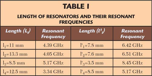
Simulated current distributions of the BPF at resonant frequency are depicted in Figure 7, with different input phase q. As shown in the figure, the input port of the filter is driven by the current (θ = 0º) while the output port is terminated to 50 Ω microstrip line. High current density distributions (red area) are mainly concentrated at the area where it is distorted by the spurlines. It is similar when the filter is driven by current (θ = 90º). Figure 8 shows the simulated current distributions of the proposed resonator at four frequencies at the input feed line, for (a) l1 = 11 mm, f1 = , (b) l2 = 13.3 mm, f2 = 4.05 GHz, (c) l3 = 8.5 mm, f3 = 5.17 GHz, (d) l4 = 12.5 mm and f4 = 3.34 GHz. As mentioned above, the proposed resonator at the input feed line generates a wide stopband with four poles corresponding to asymmetric spurlines and two quarter-wavelength open-circuited stubs. It is clear that a different resonant frequency corresponds to a different stub length or spurline length. The two resonators at the I/O feed lines with their resonant frequencies are shown in Table 1.

Figure 8 Simulated current distribution of the proposed resonator at four frequencies at the input feed line.
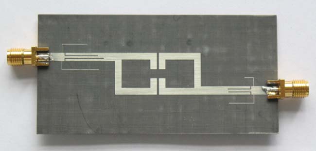
Figure 9 Photograph of the fabricated open loop BPF with spurlines and stubs.
Experiments and Measurement
Figure 9 shows the proposed BPF, which consists of two foldedopen-loop λ/2 resonators with spurlines and quarter-wavelength open-circuited stubs at the feed lines for harmonics suppression. It is fabricated on a Teflon substrate, which has a relative dielectric constant of 2.65 and a thickness of 1 mm. The measurements are carried out on Agilent Vector Network Analyzer N5230A. The simulated and measured results are shown together in Figure 10. The center frequency of the BPF is 2.44 GHz and its 3 dB bandwidth covers 112 MHz. The filter has a wide stopband with attenuation of 20 dB up to 10 GHz, using two additional harmonics suppression resonators. Its insertion loss is as low as 1.05 dB. It is obvious that the measured results are in good agreement with the simulation.
Figure 10 Comparison between measured and simulated results.
Conclusion
A novel open-loop BPF with a wide stopband for WLAN is presented in this article. Its spurious responses are effectively suppressed by adding two resonators, which are composed of asymmetrical spurlines and quarter-wavelength open-circuited stubs. Employing the harmonics suppression resonators, its stopband is controllable by adjusting the dimension parameters of two resonators. The BPF has an out of band attenuation better than 20 dB from 2.6 to 10 GHz. The measurement results have shown good agreement with the simulated results. It is believed that this newly proposed BPF can be used in WLAN systems.
References
- H.W. Liu, Y.F. Lv and W. Zheng,"Compact Dual-band Bandpass Filter Using Trisection Hairpin Resonator for GPS and WLAN Applications," Electronics Letters, Vol. 45, No. 7, March 26, 2009, pp. 360-362.
- K.A. Banitsas, Y.H. Song and T.J. Owens, "OFDM Over IEEE 802.11b Hardware for Telemedical Applications," International Journal of Mobile Communications, Vol. 2, No. 3, 2004, pp. 310-327.
- J.S. Hong and M.J. Lancaster, Microstrip Filters for RF/Microwave Applications, John Willey & Sons Inc., Somerset, NJ, 2001.
- J.S. Hong and M.J. Lancaster, "Couplings of Microstrip Square Open-loop Resonators for Cross-coupled Planar Microwave Filters," IEEE Transactions on Microwave Theory and Techniques, Vol. 44, No. 11, November 1996, pp. 2099-2109.
- Y. Zhang, J.A.R. Cruz and K.A. Zaki, "Inline and Canonical Stripline Filters with Ridge Coupling Sections for LTCC Applications," International Journal of RF and Microwave Computer-aided Engineering, Vol. 19, No. 3, March 2009, pp. 354-363.
- C.Y. Chi, K.C. Hsiung and W.M. Hang, "Design of Dual-band SIR Bandpass Filter with a Broad Upper Rejection Band for WLANs," Microwave and Optical Technology Letters, Vol. 51, No. 4, April 2009, pp. 1143-1146.
- C.M. Tsai, S.Y. Lee and C.C. Tsai, "Performance of a Planar Filter Using a 0 Feed Structure," IEEE Transactions on Microwave Theory and Techniques, Vol. 50, No. 10, October 2002, pp. 2362-2367.
- W. Xue, C.H. Liang, X.W. Dai, et al., "Design of Miniature Planar Dual-band Filter with 0 Feed Structures," Progress in Electromagnetics Research, PIER. 77, 2007, pp. 493-499.
- L.H. Weng, Y.C. Guo, X.Q. Chen and X.W. Shi, "Microstrip Open Loop Resonator Bandpass Filter with DGS for WLAN Application" Journal of Electromagnetic Waves and Applications, Vol. 22, No. 14-15, 2008, pp. 2045-2052.
- L. Li, H. Liu, B. Teng, B.H. Teng, Z.G. Shi, W.M Li, X.H. Li and S.X. Wang,"Novel Microstrip Low Pass Filter Using Stepped Impedance Resonator and Spurline Resonator" Microwave and Optical Technology Letters, Vol. 51, No. 1, January 2009, pp. 196-197.
- C. Nguyen, "Design and Performance of Novel Printed-circuit Spurline Bandpass Filters," IEEE Microwave and Guided Wave Letters, Vol. 2, No. 11, November 1992, pp. 437-438.
- C. Nguyen, C. Hsieh and D.W. Ball, "Millimeter-wave Printed Circuit Spurline Filters," 1983 IEEE MTT-S International Microwave Symposium Digest, pp. 98-100.
- W.H. Tu and K. Chang, "Compact Microstrip Bandstop Filter Using Open Stub and Spurline," IEEE Microwave and Wireless Components Letters, Vol. 15, No. 4, April 2005, pp. 268-270.