

A coupler with a through loss of less than 1.45 dB from 5 to 900 MHz was needed in a 75 ? system and only commercial couplers of 10 dB (or more) could offer this low through loss, particularly at the highest frequencies. Unfortunately, another requirement was to produce a very high RF level at the input port when the coupled port was driven. This required a high power driver with very high linearity on the coupled port. The greater the coupling loss, the higher the power required to drive the coupled port so it was advantageous to have an 8 dB coupler rather than a 10 dB coupler. It was also found that the amplifier could drive more power into a 50 ? load than a 75 ? load because of voltage swing limitations. The coupler described in this article gave some freedom not available on commercial couplers. For example, the isolated port was not used, so it could be buried inside the coupler.
The Basic Coupler
Using ideal transformers, the circuit shown in Figure 1 is an 8 dB coupler, which has a 50 ? impedance looking in the coupled port. It also has a theoretical insertion loss of 0.83 dB and a return loss of nearly 21 dB. In addition to having different turns-ratios on the transformers, the interconnections are somewhat different than for a conventional coupler. Since there is no need to access the isolated port, it is made floating. This allows the shunt transformer T1 to be an autotransformer, which simplifies construction and improves performance. This ideal 8 dB coupler has a theoretical loss of 0.83 dB, whereas the requirement allows a loss of 1.45 dB, which leaves about 0.6 dB to account for core losses, skin-effect losses and any reflection mismatches within the windings themselves. As it turns out, this 0.6 dB extra loss is a tough requirement; ordinary commercial 8 dB couplers have nearly twice this extra loss.

High Frequency Design
Since the high frequency loss is the hardest to meet, extensive modeling and measurements were done to minimize the losses and the reflective mismatches. To make the transformers perform well at high frequencies, the windings must be modeled as coupled transmission lines. The total length of the windings is restricted by the phase shifts at the highest frequency, which limits the core size and the number of turns. This, in turn, limits the wire size to fine magnet wire so skin and proximity losses alone contribute a little over 0.1 dB. Even if reflective mismatches are eliminated at high frequencies, this leaves only 0.5 dB total loss for the two cores. A clever way was found to wind the cores to give overall good performance and still provide an insertion loss of approximately 1.35 dB at 900 MHz. Although more exacting to wind (extra cost), no tuning is required. The construction details and rationale follow.

The Shunt Transformer: Modeling Turns as Transmission Lines
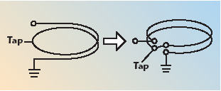
Consider the two-turn helix (in air) shown in Figure 2. It can be modeled as a simple two-wire transmission line, which is folded back upon itself. If the spacing between the turns is known, the Z0 of the line is known. The electrical length of the line is simply the length of one turn modified by er, the relative dielectric constant. Knowing just these two characteristics, high frequency modeling can quite accurately predict the performance. This assumes an air core and that there is no radiation. Even though the coil may be wound on a ferrite core, at the highest frequencies, the ferrite can be substituted with air (except for core losses). Since most of the winding anomalies show up at high frequencies, this is an excellent modeling tool. For a multi-turn helix, the assumption is that only the next adjacent turns have significant effect on high frequency performance. Under this assumption, a helix is simply the composite of multiple double-coupled transmission lines. A six-turn helix, with a tap at two turns from ground, can thus be modeled, as shown in Figure 3.
Skin and Proximity Effects
At 900 MHz, the skin effect restricts the current flow in the wires to a thin layer less than 2.54 mm thick. Additionally, the current is highly concentrated on the sides of the wire that are in close proximity to other conductors. The net result is that at approximately 0.1 dB, the copper conductor losses are approximately twice that predicted by skin effect alone. The copper losses might be slightly reduced by using a larger wire — #34 wire, for example — but core losses may increase in the series transformer because the wires are forced to be closer to the lossy ferrite in the tightly packed core hole.
Twisted Pair Transmission Lines
In the 50 to 75 ? range, the characteristic impedance, Z0, of the twisted pair is quite sensitive to the tightness of the twist because even a few spots of slight wire separation significantly change (increase) Z0. The primary function of twisting the wires is to assure intimate tight spacing of the wires, even as the pair (or triple) is wound around the core. Within reason, the tighter the twist, the lower Z0, and the more securely the wires of the pair are held in intimate contact. Instead of twisting, the same result might be accomplished if the pair (or triple) was co-extruded with insulation that held the spacing of the wires constant. The presence of the magnetic core affects the Z0 of the twisted pair. That is, a twisted pair may have a Z0 of 70 ? in air, but may increase to 75 ? when wound about a ferrite core. The reason is that the core allows more flux linkages, which increases the effective inductance of each wire. Increased inductance means a higher Z0. The increase in Z0 and the increase in core loss are closely related.
Core Losses
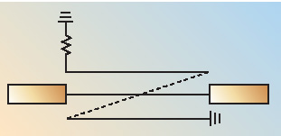
It is obvious that the core material should have low losses for a fixed number of turns. For cores with roughly equal cross-section area with six turns, the losses of commercial cores range from approximately 0.2 to 0.4 dB in a 75 ? system. Another core requirement is that it has a high enough inductance at the lowest frequencies so as to maintain high return loss and low insertion loss. A third requirement (in the present system) is that it has about 110 dB of linearity for 65 dBmV signals at the coupled port up to approximately 70 MHz. If a core is wound with a fixed number of turns and is placed across a voltage source, to a close approximation, the core losses are proportional to (Bf)2, where B is the magnetic flux density in the core and f is the frequency. At a fixed frequency, B increases linearly with applied voltage, so the core losses are proportional to B2 and hence to V2, just the same as for an ordinary resistor. If the applied voltage is held constant while the frequency is increased, B decreases as 1/f. The net result is that core losses of the shunt transformer tend to be constant with frequency, which is borne out by network analyzer measurements. At high frequencies especially, current-carrying wires that lie close to the ferrite material cause core losses. This applies especially to the series transformer. Even if there is no net magnetic flux encircling the hole in the core, there are locally intense magnetic fields around the current-carrying wires, which cause losses in the ferrite. Consider the case of just two wires passing through the hole in a core, each of which carries identical current in opposite directions (see Figure 4). Clearly, there is no net flux around the core because the canceling currents create no net H field. Yet, as shown, there are local H fields in the close vicinity of the wires, which set up local B fluxes in the core. Wherever there are B fluxes in the ferrite, there are losses, and since the currents in the wires of the series transformer tend to be constant, the local H field tends to be constant. As stated before, the core losses tend to increase as (Bf)2, so although the permeability of ferrite decreases with frequency, the local B fluxes do not drop fast enough to make up for the higher ferrite losses at higher frequencies. The net result is that core losses in the series transformer are very low at low frequency, but rise rapidly at high frequency. The skin-effect losses also rise with frequency, but rise relatively slowly as ?f.
If the two wires are moved away from the ferrite, the core losses are reduced because the local H field drops off as 1/x. Instead, if the two wires are closely paired but still touching the ferrite, local H fields are reduced and core losses are also lowered, but are still significant. Finally, if the two wires are paired and moved away from the ferrite, core losses are dramatically reduced because the H field tends to drop off as 1/x2. For lowest core losses, the lesson is to pair the wires with opposite currents and keep them away from the core surfaces.
Modeling the Series Transformer
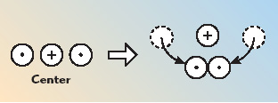
The series transformer monitors current in the main transmission path, has a turns-ratio of 3:6 and must have an isolated secondary. To set up the transmission line model, consider the diagram shown in Figure 5. The main transmission path is broken and a 75 ?, two-wire transmission line is inserted. Except for additional phase shift, the main path is not affected. However, the RF current in one conductor is of the same magnitude but opposite polarity to the current in the other conductor. Now assume that the center conductor has a wire on either side of it, each of which has a Z0 of 150 ?. The center conductor still sees a net Z0 of 75 ?, but each of the outer conductors carries only one half of the current of the center conductor. Next, connect the two outer conductors in series, as shown in Figure 6. If the lines are electrically short enough, the result is an isolated 2:1 current transformer. Finally, one end can be lifted from ground and a resistor to ground can be inserted (see Figure 7). Although the resulting current transformer is no longer “perfect” because of the phase shift between the two series sections and the imperfect ground at the resistor end, it is still good enough for this coupler application. Instead of grounding one end of the series connection, the center connection can be grounded and a resistor can be placed at each end of the series connection. This now makes a push-pull output, which may have great benefit in certain applications.

The end view of this three-wire arrangement is shown in Figure 8. Simulations indicate that the high frequency performance is somewhat improved if the outer two wires are tightly coupled to each other. In fact, simulations indicate that the Z0 of the two “outer” wires should be about 25 ?, although in practice it is difficult to get lower than approximately 40 to 50 ?, which, fortunately, still gives good performance. The “center” conductor still needs to have a Z0 of 75 ? between itself and the pair of tightly coupled outer conductors.
These two Z0 requirements can be met by pre-twisting three #36 AWG magnet wires as follows: Two of the wires are first tightly twisted (about 16 twists per inch) in the clockwise direction. This forms the two “outer” wires, which need tight coupling. Next, the “center” wire is twisted (about 8 twists per inch) about the first pair, but in a counterclockwise direction (see Figure 9). This gives a Z0 close to 75 ? between the center wire and the tightly twisted outer pair. If the center wire is twisted in the same direction around the outer pair, Z0 is much lower than 75 ? because it tends to lie close to the outer pair throughout the spiral. Twisting in the opposite direction allows the center wire to just touch the outer pair in a few spots and hence produces an acceptably higher Z0.

This specially made twisted triple should not be tightly wound on the series transformer so as to keep the current-carrying wires away from the lossy ferrite core. Ideally, the twisted triple should touch the ferrite at only four corners for each turn. This adds slightly to the turn length, but the benefits of lower core loss at high frequency outweigh the detriment of extra phase shifts.
Winding the Two-hole Core
The Series Transformer
Take the #36 pre-twisted triple with “center” wire a-A and two “outer” wires b-B, c-C and insert it in the left-hand hole of the ferrite core, as shown in Figure 10. Connect ends a and b to the solder tabs shown. Make sure there is a least one twist of a and b between the tabs and the entrance hole; do not widely space these wires. Leave end c free and unconnected for the moment. Wind two more turns (for a total of three turns) of the triple through the left-hand hole. Do not tightly wind the triple against the core in order to minimize core losses. Connect ends A and C on the tabs as shown. Again, make sure there is at least one twist of A and C between the tabs and the core hole. Now take ends c and B and snugly pull them against the existing windings, twist together and solder the connection, as shown in Figure 11.

The Shunt Transformer
Take a single #36 wire and attach it to tab e, as shown in Figure 12. Wind four turns through the right-hand hole as a single-layer, closely bunched winding. As the wire exits from the fourth turn, wrap one turn around tab f then continue winding two more turns. Connect the end at G as shown. This winding has six turns with a tap at two turns from ground. This winding may be wound tightly against the core because this winding nominally carries no current. It is all right (probably advantageous) to wind the last two turns in contact with the first turn in order to slightly increase the capacitance.
Modifications to Improve Performance

In the real world, there are always parasitic impedances, which, to some extent, can be compensated. Experimentation shows that the best overall performance is obtained by adding components and changing impedances, as shown in Figure 13. At high frequencies, the apparent turns-ratio of T1 is slightly changed by adding a small capacitor (0.2 to 0.4 pF) between the top and the tap of T1. This capacitor does not change the phase shift of T1 much, but does lower the Thevenin voltage at the tap by canceling part of the inductive impedance looking back into the tap. This extra capacitance may be incorporated into the winding arrangement of the turns of the shunt transformer. Conversely, if a small capacitor is placed between the tap and ground, the apparent Thevenin voltage at the tap is raised at high frequencies. Note also that the impedance on the isolated port has been changed to an RC network.