
In the last few years, the architectural design of satellite communications payloads has benefited from the view point of flexibility, from the adoption of Multiport Power Amplifiers (MPA). Multiport power amplifiers offer a means to combine discrete amplifiers in a way that is reconfigurable and will degrade gracefully in the event of any failures. The first reference to the basic element of a multiport power amplifier dates back to 1960,1 although the application of MPAs to satellite transponders was first envisioned at Comsat Laboratories in 1974.2
The first practical application of the MPA concept to satellite communications came many years later, when it was adopted by Nippon Telephone and Telegraph Co. (NTT) for the S-band mobile communications payload on board the experimental Japanese satellite ETS VI.3 After intense R&D activity on MPAs applied to antenna architectures performed at the European Space Agency (ESA),4 multiport power amplifier configurations were then adopted for the Inmarsat III satellites5 and for the Artemis L-band payload.6 Nowadays, MPAs are being used on board several mobile communications satellites including the Inmarsat IV fleet.7 At present, an MPA configuration is implemented in the payload at Ka-band of the recently launched Japanese Kizuna satellite (WINDS, Wideband InterNetworking engineering test and Demonstration Satellite).8
The suitability of MPAs to satellite payloads is closely related to multiple beam antenna configurations. Multiple beam coverages are adopted to provide higher edge of coverage (EOC) antenna gains and/or to implement frequency reuse schemes among the beams (that is, a more efficient use of the available bandwidth). While obtaining higher gain and reducing interference from and to other systems, they also limit the freedom to assign bandwidth and RF power resources. The application of MPAs in multibeam adaptive antenna (MAA) configurations allows efficient and flexible sharing of the total power from the power amplifiers among the beams, thus meeting varying traffic conditions9 or variable link conditions.10

Figure 1 Conventional multibeam antenna.
The conventional transmit front-end of a multiple beam satellite transponder is depicted in Figure 1. The main drawbacks of such configurations are related to failure mechanisms and traffic allocation. First, the failure of one high-power amplifier (HPA) might lead to the total loss of one beam, unless appropriate redundancy schemes are adopted. The share of the total traffic capability that can be handled at an individual beam level is limited by the size of the HPA assigned to that same beam. Moreover, there is no way to take advantage from the statistical distribution of the traffic among the beams in order to divert RF power (that is, traffic capability) where the traffic demand is higher.
In transparent satellite transponders, the proportionality between traffic capability (in terms of the number of users handled at the same time) and EIRP is evident, whether frequency division multiplexing (FDM), code division multiplexing (CDM) or single carrier per channel (SPPC) down-links are considered. A front-end configuration based on a multiport power amplifier can solve, to a great extent, all the mentioned problems.

Figure 2 MPA-based transmit front-end.
The schematic block diagram of an MPA-based transponder topology is shown in Figure 2. Before entering in more detail into the theory of a multiport power amplifier, the following main features of MPAs need to be highlighted:
- At each instant in time, the RF power assigned to one beam is a percentage of the total available RF power, all amplifiers now contributing to each individual beam.
- The failure of one HPA no longer causes the total loss of one beam, although a non-negligible reduction in RF output power has to be accounted for.
- It is possible to apportion in a completely flexible manner the total available RF power among the antenna beams, just by a proper adjustment of low level input signals.
Possible drawbacks deriving from the adoption of MPAs are the presence of post-HPA losses in the output hybrid matrix and the need for the power amplifiers to work in multicarrier operation,11 which makes MPAs less attractive in single-carrier-per-beam applications (such as in time-division multiplexed down-links).

Figure 3 Balanced amplifier configuration.
Multiport Power Amplifier Basics
In its simplest implementation, the MPA takes the form of a well known circuital configuration: The balanced amplifier network (see Figure 3). A balanced amplifier consists of two power amplifiers sandwiched between two quadrature (90°) hybrid couplers. When the voltage transmission coefficients (S21) of the two amplifiers are identical, the output power is twice that of a single amplifier and no power is lost into the isolated output port. It can also be demonstrated that, if the input voltage reflection coefficients (S11) of the two amplifiers are identical, all reflected voltages will sum to the termination at the isolated input port; the result will be a balanced amplifier perfectly matched at its input.
The balanced amplifier network is usually used to combine the power of two identical amplifiers and, in this application, the input signal is fed only to one of the two input ports. Consider now what happens when two non-coherent signals are present at the two input ports. With the aid of the superposition principle, it can be demonstrated that the signal V1, applied at input port 1, will appear at output port 4, while the signal V2, fed into input port 2, will exit from the output port 3. It is also worth noting that, regardless of the amplitude ratio between the two input signals, the two amplifiers will see at their input the same average envelope RF power; hence, they will work at the same operating point. By varying the amplitude ratio between V1 and V2, it will be possible to move continuously from one of the two opposite extreme cases, where the total RF output power comes out from either of the two output ports to the other, achieving all possible power splitting ratios between output ports 3 and 4.

Figure 4 Fig. 4 4 x 4 (a) and 8 x 8 (b) Butler matrices.
The N-port MPA Configuration
In its most general topological configuration, an MPA is composed of an array of HPAs, an input multiport network (INET) and an output multiport network (ONET). The input and output networks generally consist of two identical Butler matrices.2 A Butler matrix1 is a beam forming network12 consisting of interconnected fixed phase shift sections and 3 dB hybrid couplers. The matrix produces N orthogonal sets of amplitude and phase output coefficients, each corresponding to one of the N input ports. A Butler matrix performs a discrete Fourier transform; it is, in fact, a hardware analogue of the FFT radix-2 algorithm. Figure 4 shows 4 x 4 and 8 x 8 Butler matrices. In the 8 x 8 matrix, the circles are 90° hybrids and the numbers are phase shifts in units of π/8.
If the number of input ports and output ports of the MPA is N, N being an integer power of 2 (N = 2n), then the number of hybrid couplers composing input and output matrices will be n x 2n-1.
The fact that the order N of the hybrid matrices is an integer power of 2 does not constitute a serious limitation. Actually, when the number of beams is less than N the unused output ports of the power combining N x N hybrid matrix can be terminated by matched loads. Each 3 dB hybrid coupler can be represented by a 2 x 2 transfer matrix T relating the signal phasors at the two input ports, V1 and V2, with the phasors of the outgoing waves at ports 3 and 4, V3 and V4:
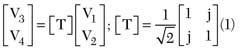
Moving from the transfer matrix of the 3 dB hybrid coupler, transfer matrices of higher order hybrid networks can be easily derived.
The possibility to eliminate the intermediate phase shifters was proposed by S. Egami and M. Kawai9 and is currently widely adopted. It is interesting to note that in their configuration, the input network divides the signal at one input port into N equal amplitude signals with phase multiples of 90°. Depending on the input port, the N equal signals fed to the HPAs will assume different phases. Such phases will, however, result from permutations of the same phase distribution, typical of the order N of the hybrid matrix.
Effects of Amplitude/Phase Errors and of HPA Failures
In an ideal MPA, the signal at one input port, after being power split in the input network (INET), amplified by the HPAs and recombined in the output network (ONET), will appear at one single output port, with no leakage of power to the other outputs. A "real-world" MPA will in fact be affected by amplitude and phase imbalance in the hybrid matrices by the finite matching between cascaded elements and by the amplifiers' gain and phase shift non-uniformities. This last contribution is usually dominant and will therefore be addressed in more detail.
Amplitude and phase errors in HPAs (whether they are travelling wave tube amplifiers (TWTA) or solid-state power amplifiers (SSPA) does not make any qualitative difference) can be classified in two main categories: systematic errors and random errors.
Systematic errors are composed of gain and absolute phase length discrepancies between the HPAs, as deriving from the intrinsic spread of their characteristics. Systematic errors can be easily calibrated out in the assembly process of the MPA by inserting suitable amplitude and phase trimmers at the HPA inputs.
Random errors derive from discrepancies in relative amplitude and phase, which cannot as easily be removed. These could come from a variety of sources, such as:
- Variations in relative amplitude/phase with frequency
- Variations in amplitude/phase with temperature
- Variations in amplitude/phase of the drive level
- Variations in amplitude/phase due to aging
All these characteristics can be summarized with the general term of amplitude and phase tracking, respectively, over frequency, temperature, drive level and aging.
Several authors have derived isolation and output power loss in an MPA configuration as a function of the rms amplitude and phase errors of the amplifiers.
Naming Δ and δ the standard deviations of amplitude and phase non-uniformities of the amplifiers, respectively, the following expressions can be applied:

where:
Pout = output power of a single port;
Ptot = total RF power of all amplifiers;
Piso = power leakage to nominally isolated output ports;
Δ = standard deviation of amplifier gain errors (ratio);
δ = standard deviation of amplifier phase errors (in radians).
It has to be taken into account that the formula listed above can only provide an average value for the MPA performance degradation. If the number of amplifiers is small, as it is in the case of a 4-port or 8-port MPA, the worst case degradations can be substantially worse (up to two or three times) than the average ones. A conservative rule-of-thumb would then suggest the consideration of a more practical worst case isolation degradation some 3 to 5 dB worse than the theoretical value.
Drastic modification of the MPA performance may then be expected when some amplifiers fail. The degradation of the MPA in terms of output power and isolation, in the case of one amplifier failure, is expressed by the following formulae:

For example, if an 8-port MPA is considered, the failure of one amplifier would result in an output power loss of 1.2 dB and an isolation degradation to 18.1 dB. The higher the order of the MPA, the less significantly it will be affected by the failure of any single power amplifier. Similar to the features usually associated with active phased-array antennas, it is here possible to speak of a "graceful degradation" feature of multiport power amplifier systems.
MPA Satellite Transponders
An ideal reconfigurable payload should allow redistributing the available RF power based on the real-time needs. Achieving this objective is strictly dependent on the architecture of the high-power section. The leading idea is to have a common power pool from which a channel can adaptively draw the power it requires. In the transmit section of an MPA satellite transponder, a plurality of input signals is transformed by the input microwave network (INET), presented to the stack of amplifiers and recombined by the output microwave network (ONET), as shown in Figure 5. The power sharing flexibility is achieved through the parallel amplification of all signals by a stack of power amplifiers (see Figure 6).

Figure 5 Single feed-per-beam with full sized multiport amplifier.

Figure 6 Basic principle of power sharing in multiport amplifier.
Intermodulation products are generated due to the nonlinear nature of the amplifier devices and recombined by the ONET and distributed among the output ports. This intermodulation products scattering can be exploited to increase multi-carrier efficiency. The cascade of the INET-ONET scattering matrices should correspond to an ideal permutation matrix. In this case, the architecture guarantees that amplified replicas of the input signals appear at the permuted output ports. The INET/ONET matrices resemble a multi-stage butterfly structure common to both FFTs and Butler matrices topologies. Assuming a constant loss per hybrid stage (α), the total ohmic output loss (in dB) of an ideal M-ports butterfly network is roughly given by

The high-power ONET realization typically involves TEM transmission line technologies at L- and S-band frequencies and waveguide technologies at Ku- and Ka-bands. Any unbalance between matrix ports results in some power lost at the desired output port and appearing elsewhere. Although the Butler matrix is the most efficient network topology to achieve orthogonal vector distributions, the choice of a different network can be suggested by the adoption of specific transmission line technology. It is worth noting that the input network operates at low power levels, hence ohmic losses can often be neglected (affecting gain but not the overall output power). To achieve the full sharing of all the RF power, the order of the multiport-amplifier should correspond to the overall number of high power amplifiers (MHPA). Unfortunately, the ONET insertion loss, mass, and layout/manufacturing complexity grow together with the number of ports (M) to the point that ONET matrices of order higher than about 16 readily become difficult to realize.
The architecture can be simplified if the MHPA-ports amplifier can be replaced with a plurality (MP) of smaller, identical M-port amplifiers, with MP·M = MHPA. These smaller M-port amplifiers require fewer hybrid stages and thus will have a lower total mass as well as lower insertion loss. The drawback of this partitioning (shown in Figure 7) stands in the reduced degree of sharing of the power.
Figure 7 Single feed-per-beam with partitioned multiport amplifier.
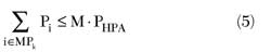
In a M-port amplifier, neglecting in a first instance the detrimental effects of the HPA's nonlinear behaviors, INET/HPAs/ONET tracking unbalances and ONET ohmic insertion losses, the maximum allocable power to a single channel PMAX is M·PHPA, where PHPA is the saturated RF power of each TWTA (that is, in the degenerate case of a single channel, the multiport-amplifier acts as a power combining network).
Generally speaking, indicating with Pi the power of the i-th channel and assuming statistical independence of the channel signals amplified by the k-th multiport-amplifier (MPk), one has:
The number of amplifier contributing to a single beam can be increased, retaining the partitioning in smaller matrices, if the beam is generated by several feed elements. In such a case, the amplitude and phase distribution at the output ports of the input network (INET) can be synthesized by a more conventional corporate power divider/combiner beamforming network4 (see Figure 8).

Figure 8 Typical multimatrix configuration for semi-active antennas.

Figure 9 ETS-6 satellite (a) and payload block diagram (b).
MPA Applications in Communications Satellite Payloads
The first satellite flying a multiport amplifier was the Japanese Engineering Test Satellite ETS-VI, launched in 1994, which suffered problems at launch and failed to reach a geostationary orbit. ETS-VI included an MPA in its Multibeam Mobile Communications Transponder, operating at S-band (see Figure 9).
In 1995 the AMSC-1 (also called MSAT-2) satellite was launched, followed in 1996 by MSAT-1. Both satellites, built by Hughes (now Boeing), included L-band hybrid matrix amplifiers to provide traffic reconfigurability in their mobile communications transponders (see Figure 10).13 In 1996, the first of the Inmarsat 3 satellites was launched. In this global mobile communications satellite, seven spot beams and a global beam are generated using a 22-element cup helix feed array and 22 SSPAs. The amplifiers are combined in four 4 x 4 matrices and one 6 x 6 matrix (see Figure 11). This configuration allows the power of each individual amplifier to be routed to any one spot beam, or any combination of spot and global beams.

Figure 10 MSAT (AMSC) satellite (a) and payload block diagram (b).

Figure 11 Immarsat-3 satellite (a) and payload block diagram (b).
In 2001, Artemis, telecommunications satellite of the European Space Agency, was launched, but, because of a launcher failure, could not reach its final geostationary orbit. After a long recovery procedure, it finally succeeded in reaching the intended geostationary orbit in 2003. Artemis, which is still operational, includes an L-band Land Mobile (LLM) payload, integrating an MPA-based transmit configuration, allowing traffic reconfigurability between a European coverage beam and three spot beams (see Figure 12).

The first satellite of the fourth generation of Inmarsat platforms, Inmarsat-4, was launched in 2005. Inmarsat-4, developed and manufactured by EADS Astrium, includes a very complex payload, including a nine meter unfurlable reflector and a sophisticated digital signal processor, to support the innovative Broadband Global Area Network (BGAN) service. The 150 SSPAs (120 are active), constituting the transmit section of the active antenna, are grouped in 15 8 x 8 multi-port power amplifiers (see Figure 13).7

Figure 14 Kizuna (WINDS) satellite (a) and Ka-band MPA (b).
One of the most limiting factors to be taken into account for satellite communications systems operating at Ka-band frequencies is rain attenuation. The application of MPAs in a Multibeam Adaptive Antenna (MAA) configuration was proposed to counteract rain attenuation at Ka-band as early as 1989.10,14 An advanced example of the use of MPA at Ka-band for traffic flexibility and for counteracting rain attenuation is offered by the recently launched Japanese Kizuna satellite (Wideband Inter-Networking engineering test and Demonstration Satellite, WINDS). The high power MPA, based on efficient TWTAs, can flexibly allocate more power to beams over rainy regions (see Figure 14).8
Conclusion
Multiport power amplifiers have found widespread use in microwave systems, especially for satellite communications. The use in satellite transponders has allowed exploitation of multiple beam antenna systems and hence the achievement of higher EOC gains and more efficient use of the frequency spectrum. The MPA technology is still very promising and worth further R&D efforts, especially in view of future applications at Ka-band.
References
- J.L. Butler, "Multiple Beam Antenna System Employing Multiple Directional Couplers in the Leadin," US Patent 3255450, June 1960.
- W.A. Sandrin, "The Butler Matrix Transponder," COMSAT Technical Review, Vol. 4, No. 2, 1974.
- D.H. Martin, Communication Satellites, Fourth Edition, AIAA Aerospace Press, 2000.
- A.G. Roederer, "Multi-beam Antenna Feed Device," US Patent No. 5115248, September 1990.
- D. Greenwood, J. Griffin and A. Roederer, "Multimatrix Beam Forming for Semi-active Antennas at L-band," ESA Workshop on Advanced Beamforming Networks for Space Applications, ESTEC, Noordwijk, The Netherlands, 1991.
- A. Sbardellati, T. Sassorossi, M. Marinelli and R. Giubilei, "The Communication Payload of the Artemis European Satellite," 15th AIAA International Communications Satellite Systems Conference, 1994.
- M.J. Mallison and D. Robson, "Enabling Technologies for the Eurostar Geomobile Satellite," 19th AIAA International Communications Satellite Systems Conference, 2001.
- I. Hosoda, T. Kuroda, Y. Ogawa and M. Shimada, "Ka-band High Power Multi-port Amplifier (MPA) Configured with TWTA for Winds Satellite," IEEE International Vacuum Electronics Conference, IVEC '07, 15-17 May 2007.
- S. Egami and M. Kawai, "An Adaptive Multiple Beam System Concept," IEEE Journal on Selected Areas in Communications, Vol. 5, No. 4, May 1987, pp. 630-636.
- M. Lisi, "A 20/30 GHz Multiple Beam Adaptive Antenna for Satellite Trunk Communications," International Conference on Electromagnetics in Aerospace Applications, Torino, Italy, 1989.
- S. D'Addio, M. Aloisio, E. Colzi and P. Angeletti, "Performance Analysis of Satellite Payload Output Sections Based on Multiport Amplifiers," Proceedings of the 10th IEEE International Vacuum Electronics Conference (IVEC 2009), Rome, Italy, 28-30 April 2009.
- P. Angeletti and M. Lisi, "Beam-forming Network Developments for European Satellite Antennas," Microwave Journal, Vol. 50, No. 8, August 2007, pp. 58-74.
- D.J. Whalen and G. Churan, "The American Mobile Satellite Corporation Space Segment," 14th AIAA International Communications Satellite Systems Conference, 1992.
- M. Lisi and G. Perrotta, "An Integrated 20/30 GHz Multibeam/Multiport Antenna System for Fixed Satellite Services," Proceedings of the ISAP, Tokyo, Japan, 1989
 Piero Angeletti received his Laurea degree (summa cum laude) in electronic engineering from the University of Ancona (Italy) in 1996. From 1997 to 2004 he was involved in aerospace systems engineering activities, joining in succession: Augusta Helicopters, Alenia Spazio, Elettronica and Space Engineering, all of Italy. He is currently a member of the technical staff of the European Space Research and Technology Center (ESTEC) of the European Space Agency (ESA), Noordwijk, The Netherlands. His current research interests include the analysis, modeling and design of telecommunication and navigation satellite systems and payloads.
 Marco Lisi is presently System Procurement Manager at the European Space Agency, in the Directorate of GALILEO Program and Navigation related activities. In this position he is responsible for the systems engineering, operations and security activities of the GALILEO project. Before joining ESA in March 2009, he was Chief Scientist at Telespazio SpA, a Finmeccanica/Thales company. Lisi has worked for 28 years in the aerospace and telecommunications sectors, covering managerial positions in R&D, engineering and programs. During his professional career, he was directly involved in a number of major satellite programs, including Italsat, Olympus, Artemis, Meteosat Operational, Meteosat Second Generation, Sicral 1A, Globalstar, Cosmo-Skymed and Galileo.