
In recent years, advances within two fields have had a major impact on how filters are designed today. One is the advent of powerful electromagnetic (EM) software, which provides results that are close to measurements. However, analysis and optimization of complete filters is often too resource and time consuming to be useable in practice. Therefore, methods that separate the entire structure into discrete components for individual EM analysis are often employed.1
The other field that has had a major impact on filter design methods is advances within the coupling matrix representation of microwave filter circuits. The coupling matrix concept was introduced in the 1970s, but general methods have recently been introduced for its synthesis.2 The coupling matrix concept has also been reformulated to accommodate couplings directly from the source and the load to internal resonators.3
The coupling matrix representation of bandpass filters is convenient since, with matrix operations, it is possible to transform between topologies whereby the best suited topology for a given problem may be found. The recent coupling matrix formulation leads to more accurate determination of practical filter characteristics; highly complex filters with multiple non-adjacent couplings are now easily synthesized.
Even though a large number of articles dealing with coupling matrix synthesis have recently been published, almost none of them go into details about how to convert the synthesized matrices into physical filters. In this article, practical filter design using the coupling matrix synthesis and simple 3-D EM simulation techniques is demonstrated. Even though EM solvers in this article are used for the designs, the adopted methods may be applied even without EM solvers available. In that case a couple of test circuits must be manufactured. Emphasis is made on practical approaches and it is demonstrated that even fairly complex x-coupled filters can be made in just one iteration. The methods are validated through measurements on manufactured coaxial cavity filters. It is also demonstrated how coupling matrix synthesis may be used to better understand and explain differences between calculated and measured filter responses.
To design microwave filters a basic understanding of coupling and coupling mechanisms is necessary. In this section the coupling mechanisms in bandpass filters are investigated. It is shown how coupling coefficients can be measured.![]()
Coupling
Figure 1 Two-pole box and associated transmission characteristic.
To demonstrate the concept of coupling between adjacent resonators, the two-pole circuit in Figure 1 is used. Two metallic resonators are enclosed in a metallic housing and loosely coupled to the in and output ports. The corresponding measured transmission characteristic (S21) is also shown. The two resonators are identical and are both resonating at frequency f0. The coupling between the resonators results in a displacement Δf of the resonance frequencies. In this case, the coupling is Δf MHz and is referred to as the coupling bandwidth. If the coupling bandwidth is divided by the ripple bandwidth BW of the filter, the normalized coupling coefficient is obtained. Therefore, the normalized coupling coefficient is given by
where Δf is the coupling bandwidth, which expressed in Hz, and M12 is the normalized coupling coefficient between resonator 1 and 2.
To minimize the influence of input and output connections on the coupling measurement, the resonators must be loosely connected to the input and output ports. If the top-point of the two peaks—or alternatively the "valley" between them—is kept below approximately -30 dB, the influence of the I/O ports can be neglected.
Figure 2 One-pole box with tapped input and associated characteristics.
The couplings, which connect the filter to the outside world, are called external couplings and are often expressed as Q values, that is external Q’s. The external Q concept can be explained by the single resonator circuit shown in Figure 2. The resonator is here coupled to the I/O port by a rod (tapped input), but could also be coupled by a non-touching capacitive disc, a loop or similar arrangement.
Also in the figure is shown a loosely coupled "sniffer" port, which allows one to do the transmission measurement shown to the right in the figure. The influence of the sniffer port can be neglected if the peak of the resonance characteristic is kept below 25 to 30 dB.
The external coupling bandwidth is found by measuring the 3 dB bandwidth of the resonance curve, denoted Δf3dB. The external Q is then found by
where it is assumed that the unloaded Q is much bigger than loaded Q so that Qext = Qloaded applies.
The external Q can also be expressed by the normalized coupling coefficient M01
where BW is the ripple bandwidth of the filter.
It is seen that a low external Q value corresponds to a wide 3 dB bandwidth and hence a strong coupling. For the tapped resonator in Figure 2, the coupling increases by moving the tap-point closer to the top of the resonator. It is also possible to determine the external Q by measuring the group delay of S11.4
Figure 3 A five-pole filter topology with positive main couplings and a negative x-coupling.
It is well known that couplings between non-adjacent resonators—x-couplings—may be used either to:
Figure 4 Three commonly used x-coupling configurations and their characteristics.
Couplings may either be inductive or capacitive and are often schematically represented, as shown in Figure 3. In the schematic circuit diagram, the numbered black dots represent resonators; the white circles represent source/load terminals (that is "connectors"). Inductive couplings are indicated by unbroken lines and capacitive couplings by a capacitor symbol. By convention inductive couplings are positive and capacitive couplings negative. A single x-coupling—bypassing one resonator (also called a triplet)—may, under certain conditions, give rejection corresponding to approximately two extra filter poles. The use of x-couplings could in such case reduce the required filter order by two, leading to a more compact filter, which at the same time may also have lower insertion loss. The penalty is that the increased selectivity gained at one side of the passband is sacrificed by reduced selectivity on the other side of the passband. Three commonly used x-coupling configurations are shown in Figure 4 for a triplet with negative (capacitive) x-coupling, a triplet with positive (inductive) x-coupling and a quadruplet with negative (capacitive) coupling. These are x-couplings bypassing either one or two resonators. The theory of cross-couplings is explained in the literature6,7 by equivalent lumped circuits and phase relationships.
The unloaded Q is not directly related to couplings but is included here because it is measured in a very similar way to the external Q. The unloaded Q is an important parameter since it is directly related to the losses of the resonator/filter and is a function of geometry as well as the materials used. If the tapped input shown previously is replaced by yet another loosely coupled "sniffer" port, the unloaded Q would be found instead of the external Q.
To estimate the unloaded Q for a circular coaxial resonator, the following expression may be used:
where
The factor of 0.75 is an estimate for imperfections like the slightly poorer conductivity that will be found in the ‘real world’, surface roughness, influence of tuning screws, etc.
Equation 4 is a modified version of an expression given by Montgomery8 for optimal unloaded Q of coaxial resonators. The original expression assumes resonator lengths, which are an integer number of a quarter wavelength ("n" is an integer). The formula, however, is also found to be useable for other resonator lengths. In Equation 4 "n" is a real number (such as 0.5 for a λ/8 resonator).
A low pass prototype filter can be described by a normalized coupling matrix M of order N+2, where N is the filter order.5 The term "low pass prototype" refers to that it is centered around 0 (zero) rad/s and has upper and lower corner frequencies of ± 1 rad/s. Once a prototype network has been synthesized, a frequency transformation is applied, which transforms the low pass prototype to a bandpass filter with the right center frequency and bandwidth.
The synthesis of low pass prototype networks—and hence filter characteristics and coupling matrices—is well described in the literature2,3,5 and will not be dealt with here. In the following, the Guided Wave Technology’s Filter and Coupling Matrix Synthesis tool (CMS)9 is used for this purpose.
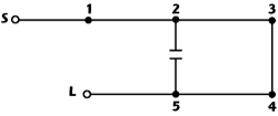
Figure 5 Folded network coupling form, fifth degree example. (Re-printed from Ref. 2).
The N+2 normalized coupling matrix M is a full description of all coupling paths in a filter. The order of M is N+2, where N is the filter order. M is a symmetric matrix with real elements Mij. The "+2" term refers to the fact that the N+2 coupling matrix is extended to include the input and output connections. Figure 5 explains the N+2 coupling matrix in more detail for the folded topology: (A) is the folded matrix form, "s" and "xa" coupling are zero for symmetric characteristics; (B) is the coupling and routing schematic. The N+2 coupling matrix includes the input/output couplings in the synthesis. Couplings may therefore be made directly from the source/load nodes to internal resonators or directly between the source and load.
Fully canonical filtering functions (that is Nth-degree characteristics with N finite-position transmission zeroes) may also be synthesized. The self couplings "s" in the main diagonal in the figure represent the resonance frequencies of the individual resonators. In an x-coupled filter the bypassed resonators will have frequencies which deviate from the center frequency - f0 - of the filter. In a filter without x-couplings the main diagonal elements will all be 0 (meaning that all resonators are tuned to f0). Outside the main diagonal, the normalized couplings—Mij—may be transformed to coupling bandwidths by multiplying by the ripple bandwidth.
Coupling matrix synthesis gives results that are fully equivalent to filters realized by lumped element (that is RLC) theory. Filters synthesized and analyzed in this way do not therefore account for effects related to the use of transmission lines as resonating elements or couplings. Couplings are assumed frequency invariant and the results obtained by coupling matrix synthesis are therefore most accurate for narrow band filters (relative BW < 10 percent) in—and close around—the passband.
This article addresses the practical aspects of making physical microwave bandpass filters based on coupling matrix synthesis. With the coupling matrix synthesis approach, a set of filter S-parameters are first created by proper choice of filter order, return loss, unloaded Q and position plus number of transmission zeros. A suitable filter topology is then defined and finally the corresponding matrix is synthesized.
This coupling matrix fully defines the filter. With this at hand, the corresponding physical filter can be designed and manufactured. To close the gap between the coupling matrix representation of a filter and the physical filter, practical directions about how to measure and calculate coupling bandwidth and external Q are given. These parameters can be determined either by use of 3D simulators or by measurements; procedures have been given for both by use of the two-pole box method.
To demonstrate the design process, two six-order coaxial cavity filters for WiMAX applications at 3.44 GHz have been designed and manufactured. Details of the design procedure and measurements on the fabricated filters can be found on the Microwave Journal web site here. The conclusion of this work is that, with coupling matrix synthesis, it is possible to design and manufacture advanced x-coupled bandpass filters in just one iteration. The results obtained are in excellent agreement with the predicted characteristics.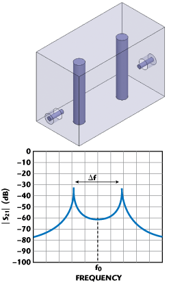
Inter Resonator Coupling


External Coupling


Cross-coupling

Unloaded Q
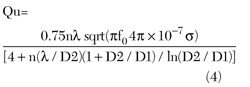
f0 = resonance frequency
σ = conductivity of metal forming cavity and resonator (silver: 6e7 Siemens/m)
D2 = cavity diameter. For rectangular cavities D2 is diameter in a circle, which has the same area as the rectangular cavity base area.
D1 = resonator diameter
h = resonator height
λ = wavelength at f0
n = h/(λ/4) resonator length expressed in quarter wavelengths. Microwave filters may be implemented in many different ways. Very often it is the loss requirement that dictates the filter technology that must be used. Table 1 gives some indications of typical unloaded Q’s for different resonator types.
Coupling Matrix Synthesis
The N+2 Coupling Matrix

Conclusion
References