
Two-arm spiral antennas usually have wideband characteristics (these antennas usually have constant beam width and circular polarization over a broad range of frequencies),1,2 and thus are suitable for communicating (transmitting and receiving) over bands of frequencies (multiple channels).
At lower frequencies, for a given size, these antennas tend to have poor performance (high S11, low gain and high axial ratio).1,2 This can be improved by increasing the diameter of the spirals. The real question, however, is can the poor performance at low frequencies be improved without sacrificing the compactness of the antenna? This article shows an innovative approach that can improve the performance of an antenna without increasing its size.
Methodology

Figure 1 An Archimedean two-arm spiral antenna.

Figure 2 Meshed FEKO model of benchmark antenna.

Figure 3 Simulated S11 and gain of the benchmark antenna.
The two-arm spiral used in this study is an Archimedean spiral, as shown in Figure 1. The benchmark for this study is a two-arm Archimedean spiral whose diameter is 6 inches. The goal is to build a two-arm spiral antenna, with reduced size, whose diameter is 4.4 inches, but has gain and return loss across the desired band (0.5 to 2 GHz) of at least that of the benchmark antenna. The 6-inch diameter two-arm Archimedean spiral antenna with a ground plane placed 2.6 inches below is shown in Figure 2, where r1 = 0.05" and r2 = 3.0" are the initial and final radius, respectively. W = 0.04" is the width of the spiral arm and S = 0.06" is the gap between turns. The antenna has 17.75 turns. Its performance is simulated (solved using MoM) in FEKO and its S11 and gain are shown in Figure 3.
The 4.4-inch final diameter two-arm Archimedean spiral antenna with a ground plane placed 2.6 inches below is shown in Figure 4. Its dimensions are r1 = 0.05", r2 = 2.2", W = 0.04", S = 0.06" and 13 turns. Its gain and S11 are simulated (solved using MoM) in FEKO and are shown Figure 5.
Comparing the two simulated performances, it is obvious that reducing the diameter resulted in lower gain and higher S11 at low frequencies (the gain decreased by 5.5 and 4 dB and S11 increased by 0.4 and 15 dB at 500 and 750 MHz, respectively). To improve the gain at the low frequencies, two helices are added such that they connect the two spiral arms to the ground plane. The two-arm spiral antenna with helices is shown in Figure 6; its simulated (in FEKO using MoM) results are shown in Figure 7.

Figure 4 Meshed FEKO model of the reduced size antenna.

Figure 5 Simulated S11 and gain of the reduced size antenna.
Comparing the simulated results for the reduced size antennas with and without helices, it is obvious that adding helices has slightly improved the gain at low frequencies (especially at 500 MHz), but still not comparable to the gain of the 6-inch diameter spiral antenna. The S11 of the antenna with helices, which remains high at 500 MHz, indicates that improving the S11 can improve the gain. To improve the S11 at the low frequencies, a dielectric absorber is added around the antenna (see Figure 8).

Figure 6 Spiral antenna with helices connecting the spiral to the ground plane.

Figure 7 Simulated S11 and gain of the spiral antenna with helices.

Figure 8 Antenna with spirals, helices and wraparound absorber.
FEKO optimization is used to determine the loss tangent (tan δ) and the thickness of the absorber. An optimization routine is set up with the goal of reaching the gain (better than -10 dB) and maximizing the return loss (minimizing S11) at 500 MHz. The optimized values found for tan and absorber thickness are 0.4 and 0.2 inches, respectively. This design is validated by fabricating a prototype and comparing the measured and simulated data. Finally, both the MoM (FEKO) and FEM (HFSS) design results are compared with the measured data. Figure 9 shows the antenna that was built with the FEKO optimization results and was later used to obtain the measured data.
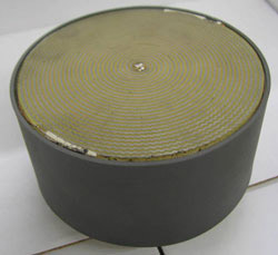
Figure 9 Two-arm spiral antenna prototype with helices and wraparound absorber.

Figure 10 Comparison of the S11 of the prototype antenna simulated with FEKO and HFSS.

Figure 11 Comparison of gains at 500 MHz.

Figure 12 Comparison of gains at 750 MHz.

Figure 13 Comparison of gains at 1 GHz.

Figure 14 Comparison of gains at 1.25 GHz.

Figure 15 Comparison of gains at 1.5 GHz.
The simulated S11 for the prototype model from FEM and MoM are shown in Figure 10. It can be seen that both the simulations agree closely, and the S11 is improved compared to the case of the 6-inch diameter spiral antenna. Figures 11 through 17 compare the gain of FEKO, HFSS and measured data at 500 MHz, 750 MHz, 1 GHz, 1.25 GHz, 1.5 GHz, 1.75 GHz and 2 GHz, respectively. The measured data and FEM data is imported into the FEKO’s post processing interface and compared with the MoM results. The axial ratios of the four antenna models are also compared in Figure 18.

Figure 16 Comparison of gains at 1.75 GHz.

Figure 17 Comparison of gains at 2.0 GHz.
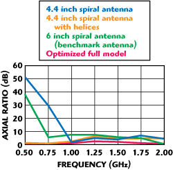
Figure 18 Comparison of the axial ratios of the four models.
Looking at Figures 10 through 16, it can be seen that the MoM simulated gain and measured gain agree quite well, but the FEM simulated gain shows a slight disagreement with the measured gain for frequencies less than 1 GHz. This is because, in the FEM simulation setup, the radiation boundary was placed at a quarter-wavelength away from the antenna at 1 GHz, due to the memory constraints. At 0.5 GHz, the radiation boundary at a quarter-wavelength away from the antenna needed more than 32 GB of RAM for a convergence result, which was not available on the host computer and thus, as expected, for frequencies greater than 1 GHz, the MoM simulated gain, the FEM simulated gain and the measured gain agree quite well.
In Figure 18, it can be seen that the optimized model has the lowest axial ratio (less than 2 dB) compared to the other three models. The optimized model has better performance (higher gain, lower S11 and lower axial ratio) and is compact compared to the bench mark antenna.

In Figure 9, it can be seen that the two spiral arm circuits are printed on a thin dielectric substrate, which is not taken into account in the MoM and FEM simulations, thus causing some small difference between the measured gain and simulated gain (FEKO and HFSS). The computation time and resource usage of MoM and FEM, for the model in Figure 8, is compared in Table 1.
Conclusion
A method was presented to miniaturize a spiral antenna, without sacrificing performance at lower frequencies. FEKO’s optimization routine (using MoM) is used effectively to accomplish the design and is verified using measured data and comparison with FEM (HFSS) simulated results. FEM (HFSS), being a field solver (volume meshing), needed far more computation time and memory than MoM (FEKO).
References
1. M.N. Afsar, Y. Wang and R. Cheung, “Analysis and Measurement of a Broadband Spiral Antenna,” IEEE Antennas and Propagation Magazine, Vol. 46, No. 1, February 2004, pp. 59-64.
2. J.A. Kaiser, “The Archimedean Two-wire Spiral Antenna,” IRE Transactions on Antennas and Propagation, Vol. 8, No. 3, May 1960, pp. 312-323.
Sandeep R. Palreddy received his BS and MS degrees in Electrical Engineering from the University of Massachusetts, Amherst. He joined the Microwave Engineering Corp., North Andover, MA, in 2008, and is responsible for the design and development of various waveguide components, broadband antennas and filters.
Rudolf Lap-Tung Cheung received his BS, MS and PhD degrees in Electrical Engineering from the University of Washington, Seattle, WA, in 1976, 1978 and 1982, respectively. From 1982 to 1985, he was a staff engineer at Transco Products Inc., Marina Del Rey, CA, where he was engaged in the research and development of advanced microwave antenna products, specializing in broadband antennas. From 1985 to 1987, he was with the spacecraft antenna research group of the Jet Propulsion Laboratory, California Institute of Technology, Pasadena, CA, where he was involved in reflector antenna design and also developed antenna measurement techniques for space and ground applications. He joined Microwave Engineering Corp., North Andover, MA, in 1994 as an antenna product manager responsible for the design and development of various broadband antennas. He currently serves as the president of the company.