 Next generation wireless systems are moving towards ever increasing data rates, higher spectral efficiency and improved quality of service. This development has largely been facilitated by advanced terminals with multiple antennas. However, the use of multiple antennas not only opens up new opportunities, but also presents new testing challenges.
For multi-antenna devices, like cellular phones in LTE and laptops utilizing WLAN, WiMAX and LTE technologies, the traditional approach of testing the antenna characteristics and the signal processing performance separately does not assess the terminal performance realistically.
This is because the conductive testing does not realistically take into account the antenna effects of multi-antenna devices. Because a multiple-input-multiple-output (MIMO) radio channel is a combination of the antenna characteristics and the radio propagation conditions, they need to be tested together in a controlled environment by a MIMO Over-the-Air (OTA) test system consisting of a radio channel emulator and anechoic chamber.
Meeting the Challenge
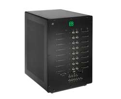
That is the challenge and the solution has been developed in the form of the EB Propsim F8 MIMO OTA emulator that utilizes the companyís patented file-based emulation approach, which is a pre-requisite to convert the geometry-based stochastic channel models to MIMO OTA models.
The emulator enables evaluation of different mobile terminal designs in a fully repeatable and realistic wireless network environment and makes it possible to test all critical parts of the mobile terminal design at once, including antennas, RF front-end and baseband processing. This eliminates the need for cables and test connectors leaving the mobile device intact, which provides more accurate results of how the device will perform in the real world.

Figure 1 The EB MIMO OTA test system in schematic.

Figure 2 The MIMO OTA anechoic chamber.
Figure 1 shows the EB MIMO OTA test system in schematic form. The EB MIMO OTA test system consists of a transmitter, EB Propsim F8 MIMO OTA channel emulator, an anechoic chamber equipped with OTA antennas (as shown in Figure 2) and a device under test (DUT) with multiple antennas.
The transmitter is connected to the radio channel emulator, which maps the geometry-based channel models to the OTA antennas so that the propagation environment inside the anechoic chamber is realistic. It is possible to create different scenarios such as indoor, urban, micro-cell, urban macro-cell, suburban and rural areas. This way, for instance, the throughput can be verified under various propagation conditions.
A Realistic Approach
The crucial challenge is to generate realistic angular and polarization behavior within the anechoic chamber to test the antenna performance of the DUT. This geometry-based information, like in 3GPP Spatial Channel Models (SCM), creates the appropriate environment at the DUT antennas. A propagation channel is described by cluster power, delays, nominal arrival and departure angles, and angle spreads of clusters on both arrival and departure ends.

Figure 3 The EB MIMO OTA application user interface.
In addition, information about the transmitter antenna arrays, including both array geometry and antenna field patterns, can be used. Also, either the terminal velocity vector or the Doppler frequency components for each cluster(s) are needed and Over-the-Air testing is the only method to analyze the antenna performance. The EB MIMO OTA application user interface is shown in Figure 3.
Radio Channel Phenomena
The most important radio channel phenomena in the geometry-based radio channel model include:
- Delay spread: Without realistic modeling of delay spread, the mobile terminal might not be adequately tested. A large delay spread makes it possible to gain from frequency diversity, but too large a delay spread results in inter-symbol-interference.
- Doppler spread: A high Doppler spread causes problems in multi-carrier systems because orthogonal sub-carriers overlap at least partly, which creates inter-carrier interference (ICI). A small Doppler spread is problematic especially in the case of flat fading, since it leads to large average fade duration and lost data packets.
- Angle spread: Angular dispersion reduces correlation between antennas. Low Rx correlation enables a capacity increase with spatial multiplexing and antenna diversity schemes. However, the correlation depends not only on angle spread, but also on antenna characteristics. Therefore, these two items have to be jointly tested.
- Polarization: The cross-polarization ratio (XPR) affects the performance of polarization diversity. Again, the real impact of XPR on DUT performance depends on the radio channel conditions and antenna characteristics.
The EB Propsim F8 MIMO OTA emulator is designed to meet the conformance and beyond-conformance testing requirements of WCDMA, HSPA, 3GPP LTE, WiMAX and IMT-Advanced.
Conclusion
The main benefit of MIMO OTA testing is the evaluation capability of the true MIMO performance of the terminal. The commercial benefits of cable-free MIMO OTA testing for mobile terminal manufacturers, wireless operators, and antenna manufacturers can be measured in terms of shorter development and verification time, shorter time-to-market, increased final product quality and savings in quality-related costs.
Operators can increase their end user experience by benchmarking the performance of different terminals in order to choose the most suitable vendor, and terminal manufacturers can optimize their design in a realistic and repeatable test environment. The development times can be shortened due to more realistic test environments, reducing the number of required field tests. From the point of view of certified test houses, MIMO OTA testing will be a totally new business area offering impressive performance measurements.
EB (Elektrobit),
Oulu, Finland,
Tel: +358 40 344 3853,
www.elektrobit.com.
RS No. 303
