 With modern electronic warfare trending toward the use of portable electronic systems in the field of battle, the environmental sealing qualities of interconnects are under scrutiny now more than ever. Conditions ranging from driving rain to dust storms can wreak havoc on the performance and longevity of electronic components without sufficient sealing. Many component engineers are choosing to use threaded connectors where blindmates would be the preferred choice because they cannot tolerate the possibility of foreign object mitigation into their enclosures. SV Microwave has developed a solution to address this concern.
Current Technologies
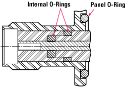
SV Microwave currently carries a line of waterproof, threaded, rigid mounted connectors (SMA, TNC among others) that provide environmental sealing using a series of o-rings. As shown in Figure 1, the dielectric is sealed to the connector body by an internal silicone rubber o-ring; the connector body is sealed against the enclosure by a panel o-ring. This design is effectively used to seal connectors in the mated and un-mated condition to IP67 standards, including full immersion in water. This is a field-tested, standard product for SV Microwave.
SV Microwave also offers a full product suite of floating blindmate connectors (BMA, BMMA, BZ, BMZ, ZMA) that are ideal for box to box mating where axial and radial misalignment must be compensated for without sacrificing RF performance. Blindmate connectors are useful when simultaneously mating multiple RF connections because of their low engagement forces. A spring mechanism is used to provide the radial and axial float, as shown in the BMA connector in Figure 2. This is standard technology and has been used extensively on airborne, ground-based and maritime platforms.

Figure 1 Waterproof RF connector sealed with o-rings.

Figure 2 Floating blindmate connector (not sealed).
The floating mechanism used in the blindmate connector separates the connector line from the enclosure, thus allowing the connector to pivot in the axial and radial directions. While an effective method of generating float, this design does not protect the enclosure from the environment.
Need for a Better Solution
SV Microwave customers asked for a connector that has the float of a blindmate and the sealing capabilities of a rigid mounted connector. This product simply does not exist in the high performance RF connector market. RF designers need a connector that can be used in applications where box to box mating is required outside a sealed enclosure such as in Line Replaceable Units. Radial and axial float are critical in these applications in order to ensure that any misalignment generated during manufacturing or install can be compensated for by the interconnect. Given the high cost and complexity of inside the box electronic components, introducing the potential for water damage or electrical failure caused by foreign object mitigation is not an option.
SV Microwave's goal was to design a connector that provides a solution to this problem by offering a high performance interconnect that is both sealed against the environment and has the floating characteristics of a blindmate connector. SV Microwave now offers the Sealed Floating Blindmate connector (SFB connector).
Electrical/Mechanical Specifications of the SFB Connector
The SFB connector utilizes the physical dimensions and electrical/mechanical performance characteristics of SV's BMZ connector line. These are defined as:
- VSWR less than 1.3:1 at 18 GHz
- Insertion Loss less than 0.3 dB at 18 GHz
- Dielectric Withstanding Voltage = 1000 V RMS
- Axial Float = 0.06"
- Radial Float = 0.02"
- Engage/disengage forces = 12 oz (max)/2 oz (min)

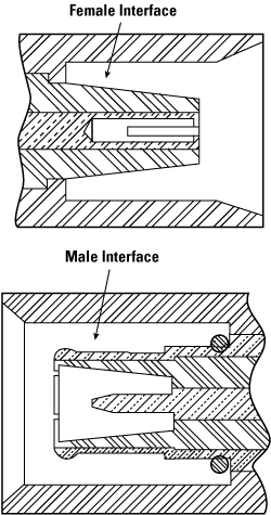
Figure 3 BMZ male and female interfaces.
The BMZ interface offers a few distinct advantages over conventional BMA (OSP) and BMMA (OSSP) connector interfaces. The first advantage is the use of splayed fingers and a recessed contact to ensure that the connector is fully grounded before the male and female contacts are mated. This is clearly shown in the cross sectional image of the BMZ connector in Figure 3.
Another advantage is the tapered dielectric, which allows higher peak power handling than the similarly sized BMMA connector by reducing the air gap between the dielectrics when mated. This design allows the BMZ connector to operate with the highest power to line size ratio in its class.
The SV Microwave SFB connector is ideal in situations where a threaded connector is unacceptable. These situations include field deployed electronic units where a quick disconnect is necessary and applications where tensile ability is restricted by protective gloves or other equipment. The blindmate connector also eliminates the potential for over-torquing the connector and damaging the interface or conversely under-torquing the connector, which could result in sub-optimal mating and decreased electrical performance.
Environmental Sealing of the SFB Connector
The SFB environment utilizes a sealing method similar to the internal and external o-ring seals discussed earlier, but with an additional proprietary mechanism that allows the connector to be fully sealed against the panel while permitting radial and axial float to the levels previously defined. The SFB connector was designed to be compliant with the International Standard for Ingress Protection per IEC 60529. This standard requires the connector to withstand ingress of foreign materials (solid particles) and the harmful effects of water.
SV's target IP requirement for the first iteration of the SFB is IP56. The first digit in IP56 (5) determines the ability of the interconnect (when sealed to an enclosure) to withstand the harmful effects of solid object ingress. Level 5 is the protection level at which the connector is guaranteed to seal against dust such that dust shall not penetrate in a quantity that interferes with satisfactory operation of the connector. This standard applies to the enclosure both in a static un-mated condition and in a dynamic field operation environment.
The second digit in the IP56 rating (6) defines the ability of the interconnect to protect against the harmful effects of powerful water jets projected against the enclosure from any direction. This product is also compliant to this specification in static and dynamic environments. This specification is designed to simulate the exposure of the interconnect to marine and intensely humid and wet environments.

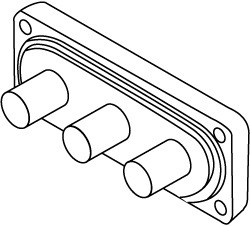
Figure 4 Multiport male block.

Figure 5 Multiport female block.
Sample Application of the SFB Connector
The initial design of the SFB connector consisted of a multiport block incorporating three connector lines. The footprint of this block was designed to minimize the center-to-center spacing of the connectors and the overall dimensions of the multiport block. Schematics of the male and female 3 port block are shown below in Figures 4 and 5.
The female multiport block consists of a panel mounted bracket sealed against the panel by a silicon o-ring and three press-in SFB connectors. These SFB connectors are cabled on the inside of the enclosure. The female connector, having no float, is fully sealed to the IP67 standard in the unmated condition making this an ideal interconnect for applications where the outside of the enclosure experiences extreme environmental conditions.
The male multiport block consists of a panel mounted bracket and three snap-in SFB connectors. These connectors are also cabled on the inside of the enclosure. The SFB male connectors contain the radial and axial float and are sealed to the IP56 standard in the unmated and mated conditions.
This is just one example of how this connector line can be tailored to a specific requirement. These connectors can be custom made to fit any application including:
- Multiport blocks in various configurations
- Termination to standard and non-standard cables
- Individual panel mounted connectors
In the case shown in Figures 4 and 5, the cable on the inside of the enclosure (for the male connector) must be flexible cable in order to accommodate the radial and axial float of the connector. The female connector can be terminated to semi-rigid cable as this connector is rigidly mounted.
The SFB connector offers a unique solution to a common problem encountered in field applications. With the electrical and mechanical performance of a floating blindmate connector and the sealing performance of a rigid mounted connector, RF design engineers now have a suitable alternative when float is required in environmentally sensitive design applications.
SV Microwave,
West Palm Beach, FL
(561) 840-1800 x152,
www.svmicrowave.com.
RS No. 301
