
Power dividers are very important components in microwave and millimeter-wave circuits. In recent years, there has been increasing demand for dual-frequency equipment due to the development of multiband technologies.
Various power dividers operating at two or more frequencies based on lumped and distributed elements have been reported,1-5 but they use increased circuit complexity and introduce parasitic effects. In this article, a novel design of a dual-band Wilkinson power divider, without additional lumped and distributed elements other than a single resistor, is presented. Moreover, the designed structure can enhance the bandwidth for small band-ratios. The two frequency bands of operation are selected by varying the electrical lengths and impedance values of three transmission lines. The proposed circuit also features a simple structure with realistic impedance values and a distributed design with reduced parasitic effect. The design parameters of the dual-band power divider are presented in explicit closed form. The validity of this analysis is confirmed through the design, simulation and experimental results for a power divider operating at 1 and 2.5 GHz.
Theory and Design Equations

Figure 1 Schematic of a dual-band Wilkinson power divider.

Figure 2 Proposed dual-band transformer structure.
Figure 1 shows the schematic representation of the proposed Wilkinson power divider for dual-band operation. The proposed impedance transformer, which is composed of two-section transmission lines and a shunt element, is depicted in Figure 2. Mathematically, the Z-parameters of this half-circuit can be derived as:

where M2, M3 and M4 are defined as:

Subsequently, these expressions can be simplified as

Since θ1 and θ2 are both functions of the two operating frequencies ƒ1 and ƒ2 (ƒ2>ƒ1), θ1 and θ2 can be expressed as

Consequently, the corresponding design parameters can be calculated by the following formulas:

Figure 3 shows the transmission line impedances versus the band-ratio ƒ2/ƒ1 of the dual-band operation. It is observed that the designed power divider can easily operate at frequency ratio ranging from 2.3 to 2.74 with normalized line impedance from 0.6 to 2.4.

Figure 3 Circuit parameters vs. frequency ratio.
Experiment
A dual-band Wilkinson power divider prototype has been fabricated on a substrate with a dielectric constant εr = 2.65 and a thickness h = 1 mm for operation at 1 and 2.5 GHz. The impedances at all ports are 50 Ω. Based on the design formulas, the impedance values of ZA, ZB, ZC can be determined as ZA = 88.7 Ω, ZB = 113 Ω and ZC = 49.3 Ω, respectively, with electrical lengths θ1 = θ2 = 0.29π.

Figure 4 Photograph of the proposed dual-band power divider.
The model simulation was performed with HFSS software and the measured data are obtained with a Wiltron 37269A network analyzer. Figure 4 shows the photograph of the designed power divider, which has an area of 72 × 51.28 mm.
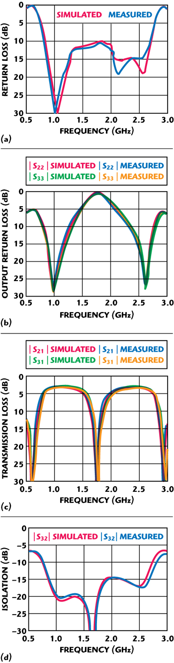
Figure 5 (a) Input return loss, (b) output return loss, (c) transmission loss and (d) isolation.
The measured performance of the designed power divider is shown in Figure 5. There is good agreement between the simulated and measured results with the dual-band operation at 1 and 2.5 GHz. The input return loss is 30.39 dB at 1 GHz and 15.01 dB at 2.5 GHz. The measured S21 values are 3.06 dB at 1 GHz and 3.28 dB at 2.5 GHz; S31 values are 3.08 dB at 1 GHz and 3.36 dB at 2.5 GHz. The isolation between ports 2 and 3 is more than 20 dB at 1 GHz and 16.88 dB at 2.5 GHz.
The designed power divider also improves the bandwidth for small band-ratios. The measured bandwidth is 240 MHz for S11, S22, S33 and S32, all better than 20 dB. The theoretical bandwidth proposed by Park6 is less than 60 MHz. The bandwidth enhancement using the proposed method becomes more pronounced as the band-ratio decreases.
Conclusion
This article presents a novel dual-band Wilkinson power divider without additional lumped and distributed elements other than a single resistor. The design procedure and closed-form equations are described. Good agreement between the simulated and measured results has been observed. The proposed structure can enhance the bandwidth as the band-ratio decreases. This simple topology makes the proposed circuit suitable for dual-band application, which will be more in demand in the near future.
References
1. R.J. Cameron, M. Yu and Y. Wang, “Direct-coupler Microwave Filters with Single and Dual Stopbands,” IEEE Transaction on Microwave Theory and Techniques, Vol. 53, No. 11, November 2005, pp. 3288-3297.
2. K.K.M. Chen and F.L. Wong, “A Novel Approach to the Design and Implementation of Dual-band Compact Planar 90° Branch-line Coupler,” IEEE Transactions on Microwave Theory and Techniques, Vol. 52, No. 11, November 2004, pp. 2458-2463.
3. J.H. Sung, G.Y. Kim, S.H. Son, H.J. Lee, Y.J. Song, Y.W. Jeong, H.S. Park and D. Ahn, “Design Method of a Dual-band Balun and Divider,” 2002 IEEE International Microwave Symposium Digest, Vol. 2, pp. 1177-1180.
4. S. Avrillon, I. Pele, A. Chousseaud and S. Toutain, “Dual-band Power Divider Based on Semiloop Stepped-impedance Resonators,” IEEE Transactions on Microwave Theory and Techniques, Vol. 51, No, 4, April 2003, pp. 1269-1273.
5. C. Monzon, “A Small Dual-frequency Transformer in Two Sections,” IEEE Transactions on Microwave Theory and Techniques, Vol. 51, No. 4, April 2003, pp. 1157-1161.
6. M.J. Park and B. Lee, “A Dual-band Wilkinson Power Divider,” IEEE Microwave and Wireless Components Letters, Vol. 18, No. 2, February 2008, pp. 85-87.