
The frequency spectrum is currently used for many applications and this resource is limited. There is also a growing demand for the use of higher frequencies, resulting from the demand from electronic warfare systems. Therefore, it is necessary to use the high band spectrum. The main advantages of working at high frequencies include more available bandwidth, smaller circuits, less interference with other services, and a less saturated spectrum.1 In this context, ultra-wideband microwave circuits have gained prominence in radiocommunications systems because many applications demand the use of large bandwidths and these kinds of circuits are of great relevance in microwave technology.
The advantage of working at high frequencies is making the development of radio-communications systems possible at frequencies of up to 30 GHz. This implies the resolution of new technological problems in addition to the design, assembly and manufact-uring problems in these frequency bands. There are currently multiple applications that work in the millimeter-wave band. Specifically, there are very interesting applications in the area of electronic warfare, such as high resolution radar or in the area of communications, such as LMDS or WiMAX systems.
Power dividers are key circuits used in many microwave applications. The function of these circuits is to divide the input signal into two or more output signals of lower power. In this article, a two-section Wilkinson power divider in microstrip technology, which covers a bandwidth of 1.585 octaves (15 to 45 GHz), has been designed, developed and measured. The measured results show good agreement with the simulations.
Basic Theory

Figure 1 Multisection Wilkinson power divider.
Multi-section Wilkinson power dividers consist of λ/4 transmissions line sections loaded with end resistances. This structure is shown in Figure 1. In such circuits, as the number of sections is increased, the bandwidth and isolation substantially increase, although insertion losses become higher. The characteristic impedances of each section can be obtained from the normalized impedances for λ/4 transformers with a transformation ratio of 2:1.2 The nominal value of each end resistor depends on the characteristic impedances, and the lower and higher frequencies of the operating band.3
Two-section Wilkinson Power Divider Design Techniques
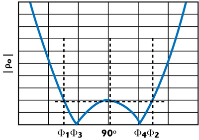
Figure 2 Reflection coefficients ρo and ρe.
The odd reflection coefficient, ρo, of a two-section Wilkinson power divider depends on the electrical length Φ of each section and can be represented as a symmetric function of approximately Φ= 90°. The location of the odd and even reflection coefficients for a two-section Wilkinson power divider is shown in Figure 2. If the design process is particularized for two sections, the input admittance (Yin,o) and the reflection coefficient ρo can be easily determined through the transmission line theory. These expressions are:


where G1 and G2 are the conductances of the resistors making up the divider, and Y1 and Y2 are the admittances of the transmission lines.
To achieve the cancellation of the reflection coefficient ρo at points Φ3 and Φ4, the real and imaginary parts of the numerator of Equation 2 must be zero. Therefore, the following expressions are obtained for the real and imaginary parts:

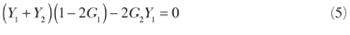
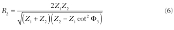
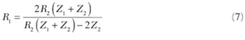
From Equations 3, 4 and 5, the values of the resistors that are part of the Wilkinson power divider can be obtained. Therefore, the resistor expressions are given by Equations 6 and 7
The expression that relates Φ3 with Φ1 can be obtained through the second degree Chebyshev polynomial: T2(x) = 2x2-1, where x = (90° - Φ)/ (90° - Φ1). The result is shown in Equation 8:

where f2 and f1 are the higher and lower frequencies of the operating band, respectively.
The design process of the two-section Wilkinson power divider can be systematized in three steps (see Figure 3):

Figure 3 Wilkinson power divider design flow chart.
- Calculation of the characteristic impedances Z2 and Z1. These impedances can be obtained from the tables for cascade λ/4 transformers.2 For an impedance transformation ratio R = 2 and a bandwidth W = 2(f2-f1)/ (f2+f1), the characteristic impedances of the transmission line sections of a two-section Wilkinson power divider can be obtained.
- Calculation of the value of Φ3 from Equation 8.
- Calculation of the resistor values at the end of each transmission line section through Equations 6 and 7.
Two-section Wilkinson Power Divider
Taking into account the considerations of the last section, an ultra-wideband power divider has been designed, with a successful response up to 40 GHz. The power divider operation specifications consist of getting insertion losses lower than 1 dB and return losses higher than 10 dB.

Figure 4 Photograph of the developed Wilkinson power divider.
A two-section Wilkinson power divider was designed and developed, and is shown in Figure 4. A 0.254 mm thick alumina substrate, with a relative dielectric constant of εr = 9.9 is used, because of the requirements of the electronic warfare systems developed by Indra Sistemas S.A. This design uses an impedance transformation ratio R = 2; the selected bandwidth is W = 2(48-12)/(48+12) = 1.2. For these values and for a Chebyshev design, a normalized impedance Z1 = 1.29545 is obtained. Therefore, the second section impedance is: Z2 = R/Z1 = 2/1.29545 = 1.5439.
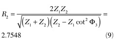
The second step is to calculate Φ3 to determine the resistor’s values. Therefore, Φ3 = 90° {1-1/√2) [(f2/f1-1)/ (f2/f1+1)]} = 51.816°, and the resistor values can be obtained from Equations 9 and 10

The Wilkinson resistors will be realized with printed resistors because it is not possible to use chip resistors at millimeter-wave frequencies. Printed resistors are obtained by depositing a certain material layer on the substrate used. The printed resistor value depends on different parameters, the resistivity and thickness of the material and the size of the resistor. An expression to calculate the resistor value in accordance with the physical dimensions is given in Equation 11

where w is the width of the resistor, l its length, r0 the material resistivity, e its thickness and res(Ω/square) is the resistance in ohms per square. Resistors of 50Ω/square will be used in the manufacturing process because it is the most common value. This fact implies that the resistor size determines the nominal value of the resistor. A crucial aspect in the circuit design is to choose the appropriate dimension of the resistors. Therefore, the discontinuities between the power divider branches can be avoided. Thus, the width of the selected resistor is the minimum set out by the manufacturing process (5.9 mils). The length of the resistor is determined by the resistor nominal value desired (13.8 mils).
Other important aspects are the discontinuities and the bends in the output branches, which must be carefully designed because these discontinuities can significantly degrade the response of the circuit. The proposed design in this article is made up of circular transmission line sections to avoid coupling between the branches.4 The discontinuity caused by the angle between the two transmission line sections does not have an equivalent circuit model and its parameters are optimized through electromagnetic simulation with the Momentum tool of the Advanced Design System software.
The bend in the output transmission line has also been optimized using Momentum to get the best circuit response. The design of the output bend is extremely important because its response affects the output return losses. In the literature, there are different bend models in microstrip technology. The most usual case is the bend whose union between the two lines is 90°. However, for this design, one of the conditions required is that the angle of the output transmission lines should be 60° on the x-axis (for mechanical considerations). Therefore, the literature models cannot be used and electromagnetic optimizations have to be used to design the bend that introduces the best possible return losses in the output ports.
Another problem in the design of the power divider is the size of the circuit transmission lines, because the substrate determines an inappropriate dimension of the second transmission line. To solve this problem, the second section of length λ/4 was replaced by a line 3λ/4 long, because the substrate could not be changed, as Indra Sistemas S.A. imposes the use of alumina to make the integration of the divider in its systems easier; this splitter is part of a wafer, where different integrated circuits for electronic warfare are developed. Although the introduction of a 3λ/4 transmission line will change the theoretical response of the divider, in particular the minimum positions, the new design continues to fulfill the bandwidth specifications.
Simulations and Measurements
To perform measurements in the millimeter-wave band, equipment, connectors and cables that work correctly up to 50 GHz are required, but it is difficult to have the equipment work properly at these high frequencies. The most sensitive elements are the connectors, whose response degrades considerably as the operating frequency of the device increases. Therefore, it is necessary to choose connectors that work up to high frequencies and to make a suitable design of the coaxial to microstrip transition to improve the device’s operating range.

Figure 5 Connector with seal.
In this project, the vector network analyzer PNA5230A, the N4693A calibration kit (both from Agilent) and connectors with a 50 Ω seal of 9 mils from SouthWest Microwave, model 1414-06SF 2.4 mm,5 have been used (see Figure 5). Reliable measurements can be taken with this measurement bench up to 50 GHz, if the effects of coaxial cables and connectors are eliminated through proper calibration.

Figure 6 Equivalent circuit of the connector.


Figure 7 Close view of the developed Wilkinson power divider.
The power divider assembly process has been done carefully, because a poor welding can significantly degrade the circuit response. Despite this, problems have been detected in the assembly of the box with the connectors. One of them has been the irregularity of the pearl outer ring, which causes a bad contact between the connector and the microstrip transmission line. Furthermore, the connectors are very delicate and deteriorate easily, because the circular section of the inner conductor connector can be deformed, causing important attenuation peaks in the circuit transmission response. The circuit simulation takes into account the effects of the connectors, which have been modeled with the equivalent circuit shown in Figure 6. In the equivalent circuit, the first coaxial represents the seal; the third coaxial simulates the pin, and the second coaxial is introduced to decrease the discontinuity effect between the seal and the pin. The capacity C1 simulates the discontinuity between the seal coaxial (CX1) and the compensation coaxial (CX2), because of a change in the outer diameter and in the permittivity of the medium. The capacity C2 models the discontinuity between the compensation coaxial (CX2) and the pin coaxial (CX3), because of a change in the outer diameter. The capacity C3 simulates the discontinuity between the pin coaxial (CX3) and the pin, resulting from a change in the propagation medium. Finally, the coaxial-to-microstrip transition is modeled by the inductor L1, the capacity C4, the resistor R and the transmission line TL1. The 2.4 mm connector 1414-06SF has been characterized previously6 through electromagnetic simulations with the CST software and by means of connector measurements. The connector equivalent circuit values are shown in Table 1. Figure 7 shows a close view of the developed Wilkinson power divider. Comparisons between the Momentum electromagnetic response and the measurements of the developed Wilkinson power divider are presented in Figures 8, 9 and 10.

Figure 8 Insertion losses of the two-section Wilkinson power divider.
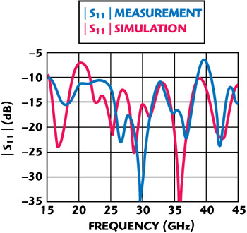
Figure 9 Input return losses of the two-section Wilkinson power divider.

Figure 10 Output return losses of the two-section Wilkinson power divider.
The measured responses are very similar to the Momentum simulations. The transmission response has a peak-to-peak ripple amplitude of 1 dB up to 38.3 GHz. Above this frequency, the response falls slightly and the peak-to-peak ripple amplitude is 2 dB in the operating band: 15 to 45 GHz. The input reflection is better than 10 dB up to 38.7 GHz. The output reflection is better than 10 dB up to 40 GHz. The response deterioration at 40 GHz is the result of the connectors mismatch.
Conclusion
An ultra-broadband power divider for the millimeter-wave band has been designed, developed and measured. The main problems of using millimeter frequencies have been studied and solved. The designed circuit presents good performance in a wide band (15 to 45 GHz). This power divider can be used in more complex circuits for electronic warfare or other applications.
Acknowledgment
This work has been supported by Indra Sistemas S.A. project P050935-556 and projects TEC2005-07010-C02 and TEC2008-02148 of the Spanish National Board of Scientific and Technology Research.
References
1. M. Alexander Morgan, “Millimeter-wave MMICs and Applications,” Thesis, California Institute of Technology, Pasadena, CA, March 2003.
2. L. Young, “Tables for Cascade Homogeneous Quarter-wave Transformers,” IEEE Transactions on Microwave Theory and Techniques, Vol. 7, No. 2, April 1959, pp. 233-237. Corrections, IEEE Transactions on Microwave Theory and Techniques, Vol. 8, No. 2, March 1960, pp. 243-244.
3. S.B. Cohn, “A Class of Broadband Three-port TEM-mode Hybrids,” IEEE Transactions on Microwave Theory and Techniques, Vol. 19, No. 2, February 1968, pp. 110-116.
4. M. Hamadallah, “Microstrip Power Dividers at mm-Wave Frequencies,” Microwave Journal, Vol. 31, No. 7, July 1988, pp. 115-127.
5. Southwest Microwave website, available: http://www.southwestmicrowave.com.
6. L.A. Tejedor-Alvarez, J.I. Alonso, J. González-Martín and P. Almorox-González, “Consideraciones Sobre el Montaje de Conectores para Optimizar su Respuesta en Bandas Milimétricas,” XXIII Simposium Nacional de la Unión Científica Internacional de Radio (URSI 2008), Book of Summaries, September 22-24, 2008, Madrid, Spain, p. 80.