
A power divider is one of the most important passive circuits used in microwave and millimeter-wave applications. In 1960, Wilkinson proposed an N-way in-phase power divider.1 He described a circularly symmetric power divider, which split a signal into N-equiphase and equiamplitude signals with an even or odd number N.
Since then, several different N-way power dividers have been proposed.2,3 All of them are for equal power dividers. In 2004, an N-way power divider with an arbitrary power split ratio was proposed by Ahn.4 In Ahn’s article, the circuit and design formulas are given, resulting in high isolation between ports. However, the structure of the divider is difficult to fabricate and it operates at a single frequency. In 2003, a small dual-frequency transformer section was introduced by Monzon,5 which operates at any two arbitrary frequencies, f1 and f2. In this article, an extension of Monzon’s analysis to the design of an improved N-way dual-frequency power divider is presented. The proposed power divider operates at two arbitrary frequencies f1 and f2, and with an arbitrary power split. The design equations are given and a new circuit is proposed, which is easy to fabricate and also has a high isolation. To verify the design method, a three-way power divider, with a power split ratio of 1: 2: 3 at both frequencies 0.915 and 2.45 GHz, which can be used in RFID applications, has been simulated and fabricated using microstrip technology. The validity of this analysis is demonstrated by experimental results.
Analyses and Design Equations
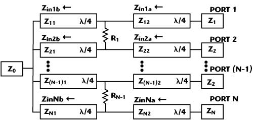
Figure 1 Diagram of an N-way arbitrary power divider.
The configuration of an N-way arbitrary power divider with arbitrary power division ratio is depicted in Figure 1, where all the transmission lines are λ/4 long, Z11, Z12, Z21,…, ZN2 represent the characteristic impedances of 2N transmission lines, respectively. If the power split ratio is P1: P2: P3…: PN = K1: K2: K3…: KN, the following equations can be obtained:
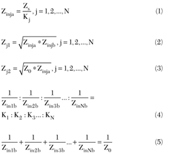
where Zs is an arbitrary design impedance, which can be determined by the design situation, Zin1b, Zin2b,…, ZinNb are the final output termination impedances and Zj1, Zj2 are the characteristic impedances of additional impedance transformers. By solving Equations 1 to 5, the design equations can be obtained:

By using Equations 1, 6, 7 and 8, a power divider with arbitrary split ratios can be designed. The isolation resistor R can be determined by


Figure 2 An equivalent transformer using two quarter-wave sections.

Figure 3 N-way arbitrary dual-frequency power divider.
In 2003, Monzon5 proposed a transformer operating at two different frequencies by splitting each quarter-wave branch into two sections with characteristic impedances Z1 and Z2 and length L, respectively. This could operate at any two arbitrary frequencies f1 and f2, as shown in Figure 2. Here, an extension of Monzon’s analysis to the design of an improved N-way dual-frequency power divider is presented. A schematic diagram of the proposed Wilkinson unequal power divider, which operates at two arbitrary frequencies and with an arbitrary power split, is shown in Figure 3.
It is necessary to determine the input and output impedances of each branch (Zin and Zout) of the unequal power divider using Monzon’s theory. Using Equations 1 to 6, ZinLa and ZinLb can be determined. Since Z0 is known, Zin and Zout are determined. The parameters of the unequal power divider can be determined by Monzon’s theory (here, f2 greater than f1 is assumed):

Experiment and Results
The three-way dual-frequency power divider was fabricated on a 1 mm thick substrate, with a relative permittivity of 2.65. The power divider is designed for f1 = 0.915 GHz and f2 = 2.45 GHz, with power division ratios of K1:K2:K3= 1: 2: 3. The simulation, with models of a real lumped component and a real substrate, was done with AWR2006 software, and the measured data was collected from an Agilent N5230A network analyzer.

The design parameters of the power divider are calculated first. Using Equation 10, the length of each transformer section is L = 30.04 mm. Let Zs = Z0 = 50Ω. Using Equation 1, the input impedances of the four transformer sections can be determined as Zin1a = 50Ω, Zin2a = 16.67Ω, Zin3a = 25Ω and Zin1b = 300Ω, Zin2b = 150Ω, Zin3b = 100Ω, respectively. The resistances R1, R2, R3 and R4 of the planar isolation resistors are selected as R1 = 82Ω, R2 = R3 = R4 = 39 Ω. The characteristic impedances and their widths and optimized lengths of the microstrip lines on Teflon substrate are given in Table 1.

Figure 4 Photograph of the fabricated dual-frequency unequal power divider.
Figure 4 shows a photograph of the fabricated power divider. The measured and simulated S-parameters are shown in Appendix A. The measured insertion loss results are approximately S21 = 8.20 dB, S31 = 5.10 dB, S41 = 3.08 dB at 0.915 GHz and S21 = 8.36 dB, S31 = 5.31 dB, S41 = 3.47 dB at 2.45 GHz, respectively. These indicate that the designed power divider can successfully separate an incoming signal into three parts with the power ratio of 1:2:3. The measured isolation is greater than -20.5 dB at 0.915 GHz and -26.7 dB at 2.45 GHz. The measured isolation between port 2 and port 4 are also greater than -21 dB at 0.915 GHz and -28.2 dB at 2.45 GHz.
Conclusion
An N-way dual-frequency arbitrary power divider is presented in this article, which fulfills an arbitrary unequal power split at two arbitrary frequencies. The structure, consisting of two sections of N transmission lines and 2N-2 planar isolation resistors, is easily fabricated. The design formulas, which are used to determine the design parameters, have been given. A good agreement between the simulation and measurement has been achieved.

Appendix A Simulated and measured S-parameters for a power split of 1,2,3 at 0.915 and 2.45 GHz.
References
1. E.J. Wilkinson, “An N-way Hybrid Power Divider,” IEEE Transactions on Microwave Theory and Techniques, Vol. 8, No. 1, January 1960, pp. 116-118.
2. U. Gysel, “A New N-way Power Divider/Combiner Suitable for High Power Applications,” 1975 IEEE MTT-S International Microwave Symposium Digest, pp. 116-118.
3. F.A. Ahargan, “Circular and Annular Sector Planar Components of Arbitrary Angle for N-way Power Divider/Combiners,” IEEE Transactions on Microwave Theory and Techniques, Vol. 42, No. 7, July 2001, pp. 1617-1623.
4. H.R. Ahn, K. Lee and N.H. Myung, “General Design Equations of N-way Arbitrary Power Dividers,” 2004 IEEE MTT-S International Symposium Digest, Vol. 1, pp. 65-68.
5. C. Monzon, “A Small Dual-frequency Transformer in Two Sections,” IEEE Transactions on Microwave Theory and Techniques, Vol. 51, No. 4, April 2003, pp. 1157-1161.