
From its beginning, one of the challenges of mobile cellular communications systems has been delivering a very stable and accurate (as little as 16 parts per billion, ppb) long-term frequency reference at each base transceiver station (BTS) to maintain accurate radio transmit and receive frequencies needed for reliable inter-cell call handoff and interference control. An even bigger challenge comes with some existing and emerging cellular architectures that require a precision (as stable as ± 1 µs) time reference to support time division duplex (TDD) operational modes. By ‘time,’ a common (relative) sense of time across the network is meant, but not necessarily absolute time of day (such as 9:35 AM PST, 12 Dec 09). Be aware that some writers’ use of ‘time’ refers to relative time, while others mean absolute time of day.
Historically, syntonization means two or more oscillators having the same frequency while synchronization means two or more clocks indicating the same time. Syntonization is often confusingly referred to as synchronization. The syntonization reference was provided by the T1 (1.544 Mbps) or E1 (2.048 Mbps) backhaul lines that connect the Time Division Multiplexed (TDM) data to the wired network. The time reference required installing a Global Positioning System (GPS) downlink to each base station (see Figure 1).
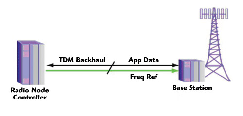
Figure 1 Cellular network syntonization via TDM backhaul.
Exploding demand for data capacity for new cellular services like mobile Web browsing, music and video downloads, in combination with intense cost pressure to support mass service demand, have led cellular network equipment manufacturers and cellular service providers to look for alternate approaches to backhaul traffic. A promising approach is to use carrier-class Ethernet equipment to provide additional data capacity at approximately one-sixth the cost per bit, while preserving service quality. Unfortunately, using Ethernet to eliminate the expensive T1 or E1 connections breaks the frequency reference provided by the TDM link, forcing operators again to install a GPS downlink at each station (see Figure 2). Thus, the Ethernet cellular backhaul solution has a missing link in providing cellular backhaul references.
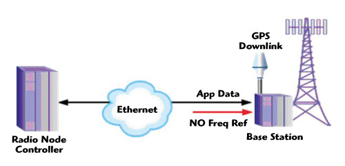
Figure 2 Ethernet backhaul with GPS reference.
Enter IEEE 1588, Precision Time Protocol
In 2002, the IEEE 1588-2002 Precision Time Protocol (PTP) standard was created to provide precision timing across Local Area Networks (LAN) for test and measurement and industrial control applications. Segments of these industries need to provide widely distributed sensors and actuators a common sense of time for coordinated measurement and control. For example, what is the distribution of stress in aircraft wings under dynamic vibration conditions? (Are the wings going to fall off?) And, how do we ensure that newsprint paper fed into a 100 meter long printing press at 30 meters per second also comes out at 30 meters per second? (Will it rip or end up in a pile on the floor?)
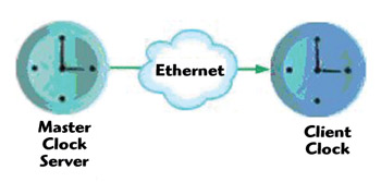
Figure 3 PTP master clock server and client Ethernet work.
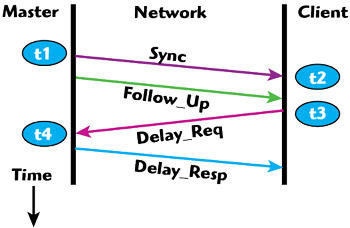
Figure 4 Timestamp packet exchange.
PTP is a time transfer protocol that allows precision time at one (Master Clock) location to be accurately transferred to another (Client Clock, also called a Slave Clock in the literature) location through an asynchronous packet network using an exchange of carefully produced timestamps of packet arrival and departure times as measured by the local clock (see Figures 3 and 4), some assumptions and some arithmetic.
If the network is constrained to use identical forward and reverse network paths, it is a good assumption that the forward and reverse packet propagation delays are equal. The offset of the two clocks is then simply:
DeltaTime = (t2-t1) - PathDelay
where PathDelay = ½[(t2-t1)+(t4-t3)]
After the Delay_Resp message, the client can calculate DeltaTime, reset itself to the master clock’s time and thus transfer the time from master to client. As the two clocks naturally drift relative to each other and propagation delay changes, new timestamps are exchanged and the process repeats, keeping the two clocks the same, or synchronized.
The Telecom Industry Sees an Opportunity
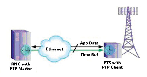
Figure 5 Conceptual PTP solution for Ethernet cellular backhaul timing.
The original PTP standard conceptually solved the Ethernet base station reference problem, shown in Figure 5, except for the not insignificant need for greatly improved frequency and time stability (to have accurate time, one must have accurate frequency), the ability to apply it beyond the LAN environment to reach cellular base stations and carrier-class reliability. With the otherwise stellar potential of carrier-class Ethernet for cellular backhaul, the telecom industry teamed with their test and measurement and industrial control partners to take on PTP for telecom timing, including base station backhaul. The result of this effort is a much-improved standard for telecom applications: IEEE 1588-2008, Precision Time Protocol, commonly called PTPv2. PTPv2 defines a significant number of improvements that support the stringent needs of base station frequency and time references.
Higher Message Rates
To ensure stability requirements can be met with inexpensive client clock oscillators, the client clock time must be updated more frequently. The revised PTP standard allows timestamp exchange (sync, follow_up, delay_request and delay_response message) rates over 128 per second, from the original maximum value of once per second. Though not explicitly required by the standard, more frequent timestamp updates do little good without accurate timestamps to exchange. Hardware timestamping, on both the master and client sides, delivers the sub-microsecond accuracy needed for base station references, as compared to software timestamping, which has jitter associated with typical software processes.
Shorter Message Formats
To keep the network bandwidth consumed by timestamp exchanges to a minimum, the original 165 octet (eight bit) message format was shortened to 44 octet sync messages by placing information about clock source and quality into a separate Announce message that need not be sent as frequently.
Unicast
The original PTP standard only supported multicast message exchanges between clock masters and clients. PTPv2 adds support for the unicast messaging needed in a telecom environment. Unicast messaging allows each client clock to only listen to messages from its master. This reduces the processing power and cost of the many client clocks typically found in a network, compared to what would be required using multicast. Also, unicast messaging allows clients of different capabilities and in different locations in the network to have different sync messaging rates. Multicast messaging requires the master to send messages to all clients at the highest rate required by any client in the network, potentially wasting network bandwidth.
Beyond LANs
Two significant innovations enable PTP to apply beyond the original LAN limitation: ITU-T Recommendation G.8261/Y.1361 and Boundary/Transparent Clocks. LANs typically consist of physical layer (OSI model Layer 1) network elements (hubs, repeaters and extenders), which have very stable propagation delays, keeping packet jitter or Packet Delay Variation (PDV; the variation in propagation delay that packets experience as they traverse the network) low, even through multiple devices (hops). On the other hand, Wide Area Networks (WAN) contain network elements (switches and routers) that operate at the link and network layers (OSI Layers 2 and 3) and make more complex packet path decisions and therefore often induce more PDV due to data control techniques and computational processing time variation.
The International Telecommunications Union (ITU) has studied the timing performance needed from packet networks to support stringent telecom industry requirements at the TDM interfaces. ITU-T Recommendation G.8261/Y.1361 identifies methods to evaluate packet network behaviors that impact time transfer performance, including Packet Delay Variation. This recommendation, in conjunction with other ITU recommendations, provides a mechanism to determine the ability of PTP masters, clients and networks to support specific telecom applications. Forthcoming ITU recommendations are expected to establish specific PTP network performance limits for selected telecom applications.
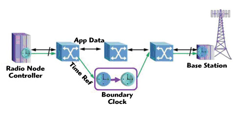
Figure 6 Using a boundary clock to improve PDV over multi-hop networks.
The other innovation is that of synchronization-friendly packet network elements. If messages need to traverse multiple switches and routers from the master clock to the client clock at the base station, Boundary Clocks or Transparent Clocks can be used to mitigate the total PDV through a cascade of network elements. The job of the Boundary Clock is to transfer precise time from one network domain (on the master side) to another network domain (on the client side). The Boundary Clock acts like both a client clock to an ‘upstream’ master clock and like a master clock to a ‘downstream’ client clock. Precise time of day is passed within the Boundary Clock from internal client to internal master through a high quality local oscillator, as shown in Figure 6. Thus, a Boundary Clock can be connected across a switch or router to eliminate its PDV contribution. The Transparent Clock similarly reduces the PDV contribution in multi-hop paths, but through the use of a trick. With accurate knowledge of its own contribution to the path delay, a Transparent Clock updates the timestamp values as they pass through the device, thereby compensating for its path delay.
Another method to improve PDV over a multi-hop path is by adding a Grand Master Clock closer to the client clocks, effectively shortening the number of hops between master and client. A Grand Master Clock (GMC) is a master clock that can provide a precise time reference independent of other master clocks.
Service Reliability
Carrier class service means very few minutes of outage per year. The enormity and complexity of typical telecom packet networks makes it likely some paths will have occasional failures. TCP/IP networking takes care of re-routing data around failed paths, but re-routing paths can create a massive path delay transient (and therefore frequency and time transient) until timestamp messages are exchanged and new PathDelay calculations are made for the new path. The PTP standard specifies that client clocks use the ‘Best Master Clock’ algorithm to scan the network for the best possible backup master clock in case of path failure and to minimize a re-routing transient.
The Clock of Gibraltar
A carrier-class frequency and time reference solution is only as good as its component parts. The origin of the frequency and time references in PTP is the GMC. This is where PTP time originates and propagates through the network to the PTP client clocks, so the quality and reliability of the GMC is key. Carrier-class GMCs start with a good quality oscillator, either an Oven-Controlled Crystal Oscillator (OCXO) or better-yet, a Rubidium atomic oscillator (RbO), to maintain the required time accuracy even if the time or frequency reference used by the GMC (such as GPS or T1 or E1) should fail for an extended period of time, a function called ‘holdover.’ A good OCXO-based GMC should be able to maintain sufficient accuracy in holdover for eight hours or more. A good RbO-based GMC should have ten times the holdover performance.
The GMC must have hardware timestamping, which, as was already mentioned, is required to precisely transfer clock time accuracy to the timestamps. Since the GMC is serving timestamps to a great many PTP slaves, the serving capacity of the GMC is also important. For example, a network with 125 client clocks within the network topology, and the client oscillator quality require an average of 16 sync and delay messages each, plus two announce messages per second to maintain the required frequency and time reference stability. The resulting GMC serving capacity needed is:
125 clients × [(16 × 2) + 2] messages/second/client = 4250 messages/second server capacity.
To deliver carrier-class reliability, one must eliminate single points of potential failure. A quality GMC will have redundant power supplies and redundant clocks with built-in hardware and network protection, which keeps the GMC operating even if one power supply or clock oscillator should fail. Wide deployment of PTP technology requires that GMCs have the ability to be remotely monitored, managed, and upgraded with new firmware to deliver new capabilities as they are developed. Because of its central role in the cellular backhaul system, it is essential that GMC suppliers stand behind their products with both hardware and software warranties, as well as providing a 24 × 7 support wherever they are deployed throughout the world.
Carrier-class GMCs are available in both a ‘blade’ type form-factor for installation in Sync Supply Units (SSU) in Mobile Switching Centers (MSC), and in a small, 1 rack unit (RU) integrated form-factor, well-suited for MSCs without SSUs and Base Station Controller/Radio Node Controller (BSC/RNC) locations.
The Client Makes All the Difference
While the Grand Master Clock is central to the synchronization solution and therefore must be extremely accurate, stable and reliable, the PTP Client has the toughest job. It lives on the other side of the network ‘cloud’ from the GMC and must contend with whatever is happening in the cloud (such as traffic levels, failures, re-routes) and locally to the client (such as temperature changes, power supply failures) to do its job.
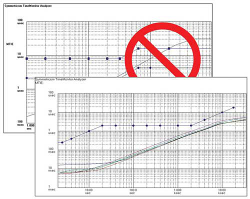
Figure 7 PTP client clock performance examples.
The fundamental choice for PTP clients is around oscillator quality, cost and form-factor. The better the client local oscillator, the better it can handle whatever is thrown its way. However, better oscillators cost more money and reducing cost is the ultimate goal with the cellular backhaul packet upgrade. To get great results with low cost oscillators, the best PTP clients support message rates up to 128 per second and use hardware timestamping to minimize induced jitter. Just as important to getting frequent low-jitter timestamps is the design of the oscillator servo, the circuit inside the PTP client that directs the oscillator to speed up or slow down after a new message is received. This can have profound effects on how well the client behaves in a challenging network environment. Figure 7 shows some sample clients’ servo performance compared to application performance requirements masks. With good design around these factors, the best PTP clients can support cellular backhaul frequency and time reference requirements with low-cost OCXOs.
Earlier, the ‘Best Master Clock’ algorithm to reduce timing transients during path re-routes and unicast support to allow message rates to be tuned for best performance was discussed. The best PTP clients support these. Also, many network operators like to manually assign PTP clients to primary GMCs, as well as backup GMCs to ensure they know exactly which clients will be affected during various network outage scenarios. The best PTP clients will allow this GMC assignment approach, as well as enabling remote management through centralized GMCs and PTP Network Management Software, simplifying system management tasks. Another valuable capability is the ability of clients to report back their performance status to their GMC, enabling operators to conveniently monitor timing quality of service.
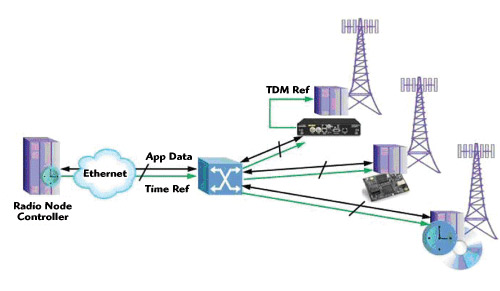
Figure 8 Stand-alone PTP translator, embedded module and embedded code solutions.
PTP clients are available as small half-rack ‘translators’ with traditional TDM outputs to enable packet timing to support existing TDM equipment. Also, leading network equipment manufacturers (NEM) are integrating PTP clients into their products. Some have chosen to use commercially available small integrated module solutions that speed and simplify integration of PTP clients into their solutions, while others are developing PTP client technology themselves or getting a hand with performance optimization by using commercially available ‘soft clients’ consisting of microprocessor and FPGA source code and licenses, as shown in Figure 8.
Go For A Test Drive
Some great news about PTP solutions is that you can now test them out to ensure they will work. Most vendors can share test data to demonstrate how their GMCs and/or PTP clients work under various network conditions—with different network elements from the various NEMs, through multiple hops across networks, with varying traffic dynamics—to better understand the performance of the end-to-end packet timing solution.
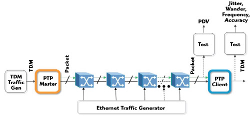
Figure 9 Timing network measurement at TDM packet interfaces.
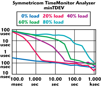
Figure 10 Packet delay variation (PDV) measurements.
Also, legacy and newly available test equipment allows one to test the performance. With a GMC, packet network and PTP client TDM translator to test, traditional TDM timing equipment can measure how well the client meets TDM performance requirements over whatever network conditions are created. Recently introduced test equipment allows moving to the packet side of the PTP client and directly measuring Packet Delay Variation (PDV) as in ITU-T Recommendation G.8261/Y.1361, as shown in Figures 9 and 10. Another handy tool for PTP solution evaluation is a network emulator, which can conveniently create various network packet delay, jitter and loss conditions. An added bonus with some network emulators is their ability to ‘playback’ delay, jitter, and loss behavior recorded on real networks to allow convenient and accurate network simulation in a lab environment. Some PTP solution vendors have consulting and evaluation services available to assist with testing PTP solutions under particular conditions of interest.
Putting It All Together
Simple deployment guidelines help ensure the best results in Ethernet cellular backhaul timing applications. Selecting a carrier-class ‘Clock of Gibraltar’ Grand Master Clock server—with the best possible performance and reliability, plus adequate capacity for the number of clients expected now and in the future in the network—forms the foundation of a solid solution. Everything flows from there, so do not scrimp on the GMC. Then, if the base station equipment already supports PTP, the client side is covered. If not, selecting a good quality PTP client ‘translator’ will support the reference needs of legacy TDM cellular base station equipment.
Deciding where to place GMCs throughout the network requires consideration of both GMC capacity and PDV seen by each PTP client. Cost considerations encourage fewer GMCs and more hops, while robustness during severe network conditions balances the solution back toward more GMCs and fewer hops. Measurements of a variety of network element cascades under various traffic conditions have led to excellent results with PTP networks up to ten hops. Sufficient GMC capacity can be checked by summing the message rate load for each client served by the GMC. If the demand exceeds the capacity of the GMC, an additional GMC can be added to divide the load. This has the added benefit of reducing the number of hops and lowering the PDV seen by some of the PTP clients. Finally, each PTP client needs to have access to a backup GMC with available capacity in the case of network failure.
The GMC may have capacity to support the desired quantity of clients, but the multi-hop network may have excessive PDV to meet the timing performance required. There are five choices under these conditions: get a better GMC, get a better PTP client, add a closer GMC, add a boundary clock, or add a transparent clock. Assuming you have already got the best GMC and PTP clients available, adding a GMC, boundary clock, or transparent clock appear to be the remaining options. As of this writing, lack of commercially availability boundary clocks and transparent clocks for telecom applications leaves adding a GMC as the practical solution to controlling PDV over wide area networks, and it has the added benefit of flattening the overall timing network.
Conclusion
Ethernet is an enabling technology for improving capacity and cost of cellular network backhauling. The missing link in this approach has been providing the precise frequency and time references to base stations. IEEE 1588-2008, Precision Time Protocol can now be used to complete this link. Best results require a carrier-class PTP Grand Master Clock, performance-optimized PTP clients, and following some basic network design guidelines. GMCs are available in both ‘blade’ form factor for Sync Supply Units (SSU) installations and small standalone form factor for remote Base Station Controller/Radio Network Controller (BSC/RNC) sites. PTP clients are available as small ‘translator’ boxes to support legacy TDM equipment, as well as modular and firmware/license packages ready for integration. Measurement tools are available to evaluate the robustness of PTP solutions. PTP GMC/client combinations are available that simplify management and monitoring of PTP timing networks.
Ethernet-over-Microwave
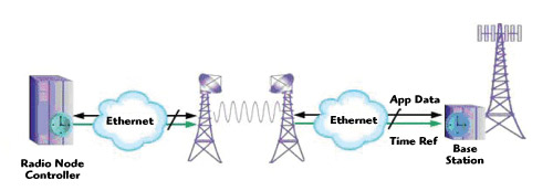
Figure 11 Cellular backhaul via Ethernet over microwave with PTP timing.
Currently, approximately eighty percent of cellular backhaul is carried over microwave link, as shown in Figure 11. To support emerging Ethernet backhaul, these links have been upgraded to support both Ethernet traffic as well as TDM traffic. A logical question is: Can these links support PTP? The short answer is ‘Yes!’ Because these links were designed to directly support the very stable frequency reference needs of legacy TDM equipment in cellular base stations, it is not surprising that recent measurements of commercial Ethernet over microwave links indicate an ability to support precision frequency and time delivery via PTP.