
A novel stop-band frequency selective surface (FSS) is presented. By adding four narrow branches to conventional square-loop FSS, the proposed FSS can achieve a good frequency stability for different oblique angles and a high frequency selective ability. An equivalent circuit model is used to analyze its transmission property. Due to the band stop characteristic of the FSS, it was used as the ground plane of a microstrip dipole antenna. In the stop-band, the FSS acts as a conventional metallic ground plane that enhances the radiation gain, but within the passband the incident waves penetrate the antenna more effectively, thus reducing the structural radar cross-section (RCS) of the antenna. The measurements of the RCS were carried out in an anechoic chamber at the National Key Laboratory of UAV Specialty Technique. Experimental and simulated results show that the cross-section of the antenna with this FSS ground plane is reduced effectively.
Recently, a growing interest has been devoted to the application of frequency selective surfaces1 in many fields such as radar systems, telecommunication, military and wireless security.2-4 According to their different transmission properties, there are two kinds of FSS. One is the passband FSS, the other is the stop-band FSS. For the application of RCS reduction, there are many reports on the utilization of passband FSS as radomes for antennas.5-8 The integration of a frequency selective surface with a protective radome can considerably reduce the RCS of the enclosed antenna outside its operating band. In contrast, there are little reports on the RCS reduction using the stop-band FSS.
Most antennas, such as dipoles, microstrip patches, etc., need a metallic ground that acts as a reflector to enhance the radiation gain. However, the metallic ground plane, which largely reflects the energy of incident waves, is one of the most important scattering components of an antenna. In order to reduce this scattering component, the conventional metallic ground is replaced by the proposed FSS. Due to the reflection property of the FSS in stop-band, it can be utilized as a ground plane to enhance the radiation gain of the antenna in place of conventional metallic ground planes. In the stop-band, the FSS operates as a conventional metallic ground plane to enhance the radiation gain. However, in the passband, most of the electromagnetic waves penetrate the antenna so that the structural RCS of the antenna can be greatly reduced. For RCS reduction of the antenna, the FSS that is used as a ground plane must possess two important bandstop properties. One is the stability of the resonant frequency with the angles of incident waves. If the resonant frequency shifts too much, the stop-band of the FSS will move outside the operating frequency band, thus decreasing the radiation gain. The other is the stop-band bandwidth of the FSS. If the bandwidth is too wide, the FSS plane will excessively reflect the incident energy beyond the operation frequency, thus increasing the RCS of antenna.
Based on the above reasons, a novel stop-band FSS is proposed and applied to the ground plane of an antenna. By introducing four narrow branches to a conventional square loop FSS, the proposed FSS has good resonant frequency stability for different incident angles. Meanwhile, its stop-band width is so narrow that more incident waves, beyond the operating frequency, can penetrate the antenna. In order to validate the method, the proposed FSS is applied to a microstrip dipole antenna for RCS reduction. Simulated and measured results show that antennas using the new FSS ground plane can simultaneously have a much lower monostatic RCS with various incident angles and little disturbances to the radiation property.
FSS Design and Results
Configuration and Formulas

Figure 1 Conventional (a) and proposed (b) FSS configurations.

Figure 2 Equivalent circuits of conventional (a) and proposed (b) FSS.
The configuration of both conventional square-loop FSS and the proposed FSS are shown in Figure 1. It can be found that the proposed FSS is a transformation form of the conventional square-loop FSS. Besides, four narrow branches are added to each element and connected to neighboring elements. Being different from conventional designs, the narrow branches introduce an additional inductance. In Figure 2, the array of FSS unit cells is represented by a single series LC circuit shunted across a transmission line of the impedance Z0, where Z0 is the characteristic impedance in free space. L and C denote the inductance and capacitance, respectively. ΔL is the additional inductance that is introduced by the narrow branches. The values of L and C are determined as follows:9,10

where


with


Figure 3 Detailed configuration of the proposed FSS structure.
εeff is the effective dielectric permittivity of the substrate of FSS. According to Sung, et al.10 if one side of the FSS is backed by a dielectric substrate whose thickness is greater than 0.05 dielectric wavelength, the dielectric slab will behave with an effective permittivity εeff = (1+εr)/2, which affects the capacitive impedance value of the equivalent circuit in Equation 2. Each element of the proposed FSS lattice consists of four connecting branches, as shown in Figure 3. These narrow branches, together with insets at the connections, introduce an additional inductance ΔL. According to the equivalent circuit shown previously, the resonant frequency of the conventional square-loop FSS can be determined as follows:

Similarly, the resonant frequency of the proposed FSS is determined as follows:


Figure 4 Transmission coefficients for different incident angles: (a) Theoretical coefficient for conventional FSS with infinite unit cells (b) theoretical coefficient of the proposed FSS with infinite unit cells; and (c) measured coefficients of the proposed FSS with 10 × 10 unit cells.
The bandwidth of a FSS is related to ![]() .7 From Equation 9, it can be found that the inductance L is smaller than that of the conventional one. Therefore, the proposed FSS has a narrower bandwidth compared to conventional one. This prediction will later be validated by curves shown in Figure 4.
.7 From Equation 9, it can be found that the inductance L is smaller than that of the conventional one. Therefore, the proposed FSS has a narrower bandwidth compared to conventional one. This prediction will later be validated by curves shown in Figure 4.
Theoretical and Experimental Results
An S-band FSS with the proposed structure was designed. The parameters of the proposed FSS, whose resonant frequency is 3 GHz, are p = 18 mm, d = 17.5 mm, c = 5 mm, s = 1 mm, g = 0.5 mm, b = 0.5 mm, t = 3.5 mm, and the thickness and dielectric permittivity of the dielectric substrate are h = 1.5 mm, εr = 6, respectively.
A FDTD method is used to simulate the proposed FSS and the conventional square-loop FSS, respectively. In Figures 4 (a) and (b), the simulated results of oblique incident angles are presented for vertical perpendicular polarization (TE). As shown, for 0°, 30°, 45° and 60° angles, the resonant frequencies of the proposed FSS are 3.04, 3.02, 3.01 and 3.0 GHz, respectively. The -10 dB stop-band bandwidths for 0°, 30°, 45° and 60° angles are 370, 320, 240 and 180 MHz, respectively. However, for 0°, 30°, 45° and 60° angles, the resonant frequencies of the conventional square-loop FSS are 3.01, 3.17, 3.21 and 3.25 GHz, respectively. The -10 dB stop-band bandwidths for 0°, 30°, 45° and 60° angles are 2.13, 1.36, 1.15 and 0.83 GHz, respectively. With the incident angle of 60°, the maximum resonant frequency shift of the proposed FSS is 1.3 percent whereas the resonance shift is 8 percent for the conventional FSS. Hence, compared with conventional FSS, the proposed FSS has a better stability of resonant frequency with different incident angles. Similarly, with the incident angle of 60°, the -10 dB stop-band bandwidth of the proposed FSS is 6 percent but is 27 percent for the conventional FSS. As Equation 9 predicts, the proposed FSS has a narrower bandwidth than the conventional FSS.

Figure 5 Photograph of the fabricated 10 × 10 cells FSS (a) and a microstrip dipole with the proposed FSS ground plane (b).
A photograph of the fabricated proposed FSS with 10×10 unit cells is illustrated in Figure 5 (a). The measurement of the proposed FSS was carried out in an anechoic chamber. The measured transmission coefficients for different incident angles are shown in Figure 4 (c). For 0°, 30°, 45° and 60° angles, the measured resonant frequencies are 3.04, 2.98, 3.0 and 3.06 GHz, respectively. Due to the finite elements of the fabricated FSS, the measured results are a little different from theoretical results of an infinite FSS. However, it can be seen that the measured and simulated results are in good agreement.
Application to RCS Reduction
There are many methods available to reduce the RCS of antennas. Radar absorbing materials (RAM), lumped loads11 and distributed loads12 have been used for controlling the RCS of antennas. In addition, the scattering response of antenna can be tuned to minimize the RCS at threatened frequencies by control of a varactor.13 However, these methods for RCS reduction always lead to complicated antenna structures or high cost.
Unlike the methods discussed above, the stop-band FSS is used as the ground plane of the antenna in order to reduce its RCS. If the operating frequencies of the antenna are within the stop-band of the FSS, the FSS will reflect the incident waves so that the FSS operates as a conventional metallic ground plane. Beyond the operating band of the antenna, due to the spatial filtering property of the FSS, the incident waves penetrate the antenna, which can effectively reduce the structural RCS of the antenna. In order to show validation of this method, a microstrip dipole antenna operating in the stop-band of the proposed FSS ground plane is presented.
Radiation of Antenna with FSS Ground Plane

Figure 6 Simulated and measured radiation patterns with different ground planes.
The microstrip dipole antenna with the proposed FSS is shown in Figure 5 (b). The FSS ground plane consists of 5×6 units. In order to research the effect of the FSS ground plane on the radiation of the antenna, the radiation gain pattern is simulated and measured in an anechoic chamber. Figure 6 shows the simulated and measured results of the same antenna with different ground planes at the central operating frequency of 3 GHz.
As shown, the radiation pattern of the antenna with the FSS ground plane varies little as compared to the antenna with a metallic ground plane. Due to unperfected reflection of FSS, the gains of antenna with FSS ground plane decrease approximately 1 dB in both E and H plane as compared to an antenna with metallic ground plane. By now, the validation of the proposed FSS ground plane for antenna application has been proven.
RCS Research of Antenna with FSS Ground Plane

Figure 7 Photo of RCS measurement of antenna with proposed FSS plane with 5 × 6 unit cells (a) and antenna with metallic plane (b) in two places in anechoic chamber.
Once the validation of the proposed FSS for the application on an antenna is proven, the next step is to see what effect the proposed FSS will bring to the RCS reduction of an antenna. The monostatic RCS of the antenna with different ground planes is simulated with Ansoft HFSS and measured in an anechoic chamber at the National Key Laboratory of Specialty Technology. The measurement was carried out in a frequency range of 1 to 10 GHz. A metallic sphere whose diameter is 150 mm is used as a calibration object. Figure 7 shows the photograph of the measurement of the same antenna with FSS and metallic ground plane, respectively.

Figure 8 Simulated (a) and measured (b) monostatic RCS of antenna for normal incident angle.
Figure 8 shows the simulated and measured monostatic RCS of an antenna with different ground planes at normal incident angle, respectively. According to Figure 8 (a), outside the operation band of the antenna, the RCS of the antenna with proposed FSS ground plane is reduced considerably at some wide bands of 1 to 3 and 4 to 8 GHz. The maximum reduction of RCS is 22 dBsm at 2.2 GHz. In contrast, inside the operation band of the antenna, due to the stop-band property of FSS, the RCS has not been reduced instead of increasing about 0.9 dBsm at 3.1 GHz. Similarly, in Figure 8 (b), outside the operation band of the antenna, for three bands of 1 to 3, 4 to 8 and 8.5 to 10 GHz, the RCS of the antenna is reduced effectively by the proposed FSS ground plane. The maximum reduction of RCS is 40 dBsm at 2.1 GHz.

Figure 9 Simulated monostatic RCS of antenna of incident angle θ = 30° and φ = 45°.
Figure 9 shows the simulated RCS of the antenna with different ground plane at incident angle of θ = 30° and φ = 45°. Although the RCS of the antenna with FSS ground plane increases at 5 to 7 GHz, the FSS ground plane reduces the RCS of the antenna considerably in two wide bands of 1 to 5 and 7 to 10 GHz. The maximum reduction of RCS is 15 dBsm.
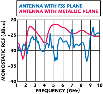
Figure 10 Simulated monostatic RCS of antenna of incident angle θ = 60° and φ = 45°.
When the incident angle is θ = 60° and φ = 45°, as Figure 10 shows, the FSS ground plane reduces the RCS of the antenna almost for the full band of 1 to 10 GHz. The maximum reduction of RCS is 12 dBsm at 5.1 GHz. But in two narrow bands of 6.8 to 7.1 and 9 to 10 GHz, the RCS of the antenna increase 2 and 3 dBsm, respectively.
Discussion
For normal incident angle, the measured RCS is approximately 10 dBsm smaller than theoretical RCS for low frequencies. Because for low frequencies, the background environment of the anechoic chamber becomes worse, leading to some error for the measured results. When the frequency becomes higher, the effect of this error becomes smaller, as Figure 10 shows, the simulated and measured results are in good agreement.
Conclusion
By adding four narrow branches to a conventional square-loop FSS, the proposed FSS can achieve good stability of resonant frequency and a narrow stop bandwidth. This has been demonstrated through both simulation and experiments. For the proposed FSS, the maximum shift of resonant frequency occurs at the incident angle of 60° and the maximum shift is 1.3 percent whereas the resonance shift is 8 percent for conventional FSS. The -10 dBsm bandwidth with incident angle of 60° is 6 percent for the proposed FSS and 27 percent for the conventional FSS.
Good frequency stability of the design ensures that the FSS will be used as a ground plane of antennas in order to reduce the RCS of antennas. Simulated and measured results show that, in contrast to conventional metallic ground plane, the proposed FSS ground plane considerably reduce the monostatic RCS of a microstrip dipole antenna for a wide frequency band in 1 to 10 GHz.
References
1. R. Mittra. C.H. Chan and T. Cwik, “Techniques for Analyzing Frequency Selective Surfaces – A Review,” Proceedings of the IEEE, Vol. 76, No. 12, 1988, pp. 1593-1615.
2. T.K. Wu, “Four-band Selective Surface with Double-square-loop Patch Elements,” IEEE Transactions on Antennas Propagation, Vol. 42, No. 12, 1994. pp. 1659-1663.
3. M. Gustafsson, “Investigation of Antenna Interaction with an FSS Radome,” Antenna Propagation Society International Symposium, Vol. 2, 1989. pp. 1076-1079.
4. G.I. Kiani, A.R. Weily and K.P. Esselle, “A Novel Absorb/Transmit FSS for Secure Indoor Wireless Networks with Reduced Multipath Fading,” IEEE Microwave Wireless Components Letters, Vol. 16, No. 6, 2006. pp. 378-380.
5. G. Gerini and L. Zappelli, “Multilayer Array Antennas with Integrated Frequency Selective Surfaces Conformal to a Circular Cylindrical Surface,” IEEE Transactions on Antenna Propagation, Vol. 53, June 2005, pp. 2020-2030.
6. D. Lee, S. Chakravarty and R. Mittra, “Design of Dual-band Radomes for High Off-normal Incidence Using Frequency Selective Surfaces Embedded in Dielectric Media,” Electronics Letters, Vol. 36, August 2000, pp. 1551-1553.
7. R. Mittra and D.W. Lee, “Analysis of a Frequency Selective Surface (FSS) Radome Located in Closed Proximity of a Phased Array Antenna,” IEEE Antenna Propagation Society International Symposium, Vol. 2, 1989, pp. 1076-1079.
8. V.V.S. Prakash and R. Mittra, “Analysis of Interaction between Microwave Antennas and Frequency Selective Surface (FSS) Radomes,” IEEE Antenna Propagation Society International Symposium, Vol. 4, 2003, pp. 404-407.
9. R.J. Langley and E.A. Parker, “Equivalent Circuit Model for Arrays of Square Loops,” Electronic Letters, Vol. 18, February 1982, pp. 294-296.
10. G.H.H. Sung, K.W. Sowerby and A.G. Williamson, “The Impact of Frequency Selective Surfaces Applied to Standard Wall Construction Materials,” Antenna Propagation Society International Symposium, 2004. pp. 2187-2190.
11. D.M. Pozar, “Radiation and Scattering from a Microstrip Patch on a Uniaxial Substrate,” IEEE Transactions on Antenna Propagation, Vol. 2, August 1987, pp. 613-621.
12. J.L Volakis, A. Alexanian and J.M. Lin, “Broadband RCS Reduction of Rectangular Patch by Using Distributed Loading,” Electronic Letters, Vol. 28, December 1992, pp. 2322-2323.
13. J.T. Aberle, M. Chu and C.R. Birtcher, “Scattering and Radiation Properties of Varactor-tuned Microstrip Antennas,” IEEE Antenna Propagation Society International Symposium, Vol. 4, July 1993. pp. 2229-2232.
Bao Lu received his BS degree in Electronic Engineering from XiDian University, Xi’an, China, in 2004, and is currently working toward his PhD degree in Electromagnetic and Microwave Technology at XiDian University, Xi’an, China. His research interests include electromagnetic scattering of objects and antennas, and radar imaging and its application on RCS measurement.
Shu Xi Gong is currently a professor and tutor at XiDian University. His main interests include electromagnetic theory, scattering and radiation.
Jin Ling received his BS degree in Electromagnetic Field and Microwave Technology from Xidian University, Xi’an, China, in 2006, where, since 2007, he has been working toward a dual MS-PhD degree. Since 2007, he has been working in the National Key Laboratory of Antennas and Microwave Technology at Xidian University. His present research interest includes electromagnetic computation and electromagnetic scattering.