When measuring small production antennas and antenna-based assemblies, as well as for the development of millimeter-wave antennas, a requirement exists for a measurement system that is not only small but also fully portable. Designed to fulfill these needs is ORBIT/FR’s Mini-Compact Range Chamber, which is a portable test facility that incorporates a ‘mini-compact range’ reflector system featuring a rolled edge design with a nominal 12-inch diameter quiet zone. What’s more, the range has been designed for easy transportation between production locations for efficient test asset utilization.
Main Design Features
The design is such that the compact range is integrally mounted into a portable anechoic chamber assembly that is 60 inches high, 52 inches wide and 84 inches long. The chamber features a ‘hatch’ type opening that allows easy access inside the chamber interior, and the entire assembly is easily moved on a built-in set of casters. An AL-060-1P miniature positioner allows for feed polarization adjustment, and an AL-160-1 positioner provides azimuth rotation for the antenna under test.
Corrugated feeds facilitate precise control of the reflector illumination within the small chamber assembly resulting in excellent quiet zone performance. The integrated facility utilizes the Agilent Performance Network Analyzer (PNA) and the 959Spectrum or MiDAS Antenna Measurement Workstation to provide a complete small antenna, high frequency measurement solution.
Significant features include a compact range featuring a 12-inch diameter quiet zone, implemented in a small corner-fed rolled edge reflector assembly with maximum physical dimensions of 2 feet square. It provides a long focal length for low levels of cross-polarization and provides low cost reflector fabrication using aluminum technology.
As the entire assembly is mounted on casters, the system can be easily transported to and from various sites, thus facilitating high usage efficiency for the test room, while access gained by the hatch opening allows full and convenient access to the feed and antenna-under-test (AUT) areas.

Fig. 1 Corrugated compact range feed.
The compact range dimensions are minimized by virtue of the use of a rolled edge for the termination of the reflector, as well as by designing for lowest operating frequencies in the X-/Ku-band region. The chamber’s cross sectional dimensions are kept to a minimum by the use of 4 and 6 inch absorbers throughout. Also, the control of extraneous energy within the chamber is facilitated by the tight control of the reflector illumination using a corrugated horn design specially tailored to the geometry of the long focal length reflector. A corrugated feed is shown in Figure 1.
The AL-160-1 azimuth positioner rotates the AUT. It has a turntable diameter of approximately 6 inches and is only 6 inches high, thus offering a low profile test mount for the small millimeter-wave antennas under test. The AL-060-1 positioner is even smaller, with a turntable diameter of only 2.5 inches and is used for adjusting the feed polarization. Both axes are equipped with encoders for position feedback. DC motors are utilized, each driven by a dedicated pulse width-modulated (PWM) DC amplifier incorporated within a power control unit (PCU). Overall motion control is implemented using a digital servo loop to achieve the precise accuracies needed for testing millimeter-wave antennas.
Performance

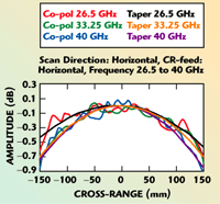
Fig. 2 Typical amplitute taper and ripple at Ka-band.
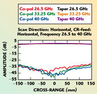
The chamber performance is driven by the compact range design. Typical amplitude scans are shown in Figure 2 for Ka-band frequencies, while phase ripple performance is shown in Figure 3. The precision machining of the reflector surface, along with the optimized rolled edge design results in excellent phase ripple performance throughout the operating frequency range. Cross-polarization performance exceeds 30 dB down over the entire quiet zone, primarily due to the long focal length chosen. Typical performance is shown in Figure 4.

Fig. 3 Typical phase taper and ripple at Ka-band.

Fig. 4 Typical cross-polarization levels at Ka-band.
Quite often, Fourier Transforms are used to determine the source of extraneous signals entering the quiet zone to verify that no major contributions to quiet zone performance come from within the chamber, such as the feed area. An analysis was performed to determine whether this was in fact an issue for the mini-compact range chamber. Results showed that by and large any extraneous signals were better than 50 dB down. A windowing function applied to a uniform distribution is used as the baseline, and is compared to the measured data with the same window applied. The error term is then evaluated for an indication of performance quality. A typical plot of such an analysis is shown in Figure 5. This analysis shows that for a small rolled edge reflector in a small chamber, there are no significant reflections from the absorber treatment, reflector edge effects or feed coupling.

Fig. 5 Transformed data sets for a windowed baseline and measured data, shown with the error component at 40GHz.
Conclusion
This mini-compact range and chamber assembly has been designed to enable cost effective testing of microwave and millimeter-wave antennas, with a 1 ft diameter quiet zone. The system provides a portable, accessible test tool for small antenna designs. Excellent sensitivity can be achieved with a consolidated, integrated instrumentation test set such as the Agilent PNA. Measurements indicate good amplitude and phase performance can be achieved over the complete test zone, along with a low level of cross-polarization. Additional information can be obtained via e-mail at info@orbitfr.de.
ORBIT/FR – Europe GmbH,
Munich, Germany
+49 8106 996060,
www.orbitfr.com
