
There has recently been much research on broadband and multi-band antennas for various wireless communication systems. The IEEE has issued regulations for the wireless local area network (WLAN, 802.11a/b) since 1999. The development of WLAN has already reached maturity and has become fairly universal. The development of antennas used on mobile communication devices is extremely important. The advantages of the printed dipole antenna1,2 include low profile, light weight and low cost. Furthermore, it is very suitable for installation in notebook computers. A dipole antenna was reported2 where an embedded U-shaped slot in the two rectangular arms produced two additional dipole arms. These two dipole arms enable the dipole antenna to generate a lower and a higher frequency resonance. Similarly, a different shaped slot, embedded in the dipole antenna, can produce two additional dipole arms.3,4 Two designs5,6 of monopole antennas consist of two strips with the same width and different length. These strips can generate different operating frequency bands.
In this article, a rectangular dipole antenna is demonstrated, where two embedded T-shape slits generate a new resonant mode to achieve dual-band operation from 2.23 to 2.62 and 4.84 to 5.38 GHz for WLAN applications. The proposed antenna is fed with a 50 Ω mini coaxial line. The advantages of the proposed antenna include small size, low cost, easy fabrication. It is very suitable for installation in a notebook computer, Personal Digital Assistant (PDA) and other mobile communication devices. Detail design steps and experimental results for the designs are studied and investigated in this article.
Antenna Design

Figure 1 Proposed WLAN antenna geometry.
The configuration of the proposed antenna is shown in Figure 1, with dimensions of Wsub = 7 mm, Lsub = 43.96 mm and H = 0.8 mm. The proposed dual-band dipole antenna is printed on an FR4 substrate with a relative dielectric constant εr = 4.4 and a thickness H = 0.8 mm. The proposed antenna is fed in the middle of the structure and connected to a 50 Ω mini coaxial line. The basis of the antenna structure is two rectangular arms with dimensions of W1 = 5 mm and L1 = 16.53 mm. The horizontal patch is combined with a triangular patch and a rectangular patch (W2 = 2 mm, L2 = 5 mm), forming a rectangular dipole plate. The left and right plates are symmetrically placed on both sides of the feed point, with a feed gap G fixed at 0.9 mm. The dipole antenna1 can generate a frequency resonance at 2.4 GHz. In this design, a T-shape slit, is embedded in each arm of the rectangular dipole antenna to generate a new resonant mode at 5.2 GHz. Combining the 2.4 GHz band of the rectangular dipole antenna and the 5.2 GHz band newly generated meets the requirements of WLAN systems.
Experimental Results and Discussion
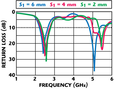
Figure 2 Measured return loss for different S1.

Table 1 Resonance characteristics for different S1 lengths.
In this section, dipole antennas with various parameters (S1, S2 and L3) were constructed and studied to demonstrate the performances of the proposed design. The simulated results are obtained with Ansoft High Frequency Simulation Software (HFSS). Figure 2 shows the measured return losses of different slit lengths S1 with other dimensions: G = 0.9 mm, L1 = 16.53 mm, L2 = 5 mm, L3 = 5 mm, L4 = 6 mm, W1 = 5.mm, W2 = 2 mm, W3 = 2.mm and S2 = 1 mm. The resonance characteristics of these antennas are listed in Table 1. When S1 decreases, the lower frequency is slightly shifted up from 2.43 to 2.54 GHz, and the higher frequency is markedly shifted up from 5.05 to 5.41 GHz.

Figure 3 Measured return loss for different S2.

Table 2 Resonance characteristics for different S2 lengths.
The measured return losses for various slit lengths S2 are shown in Figure 3 with S1 = 6 mm. The resonance characteristics of these antennas are listed in Table 2. The higher resonance frequency is markedly shifted up from 5.05 to 6.76 GHz when S2 is increased.

Figure 4 Measured return loss for different L3.

Table 3 Resonance characteristics for different L3 lengths.
Figure 4 shows the measured return losses for different lengths L3, with S1 = 6 mm and S2 = 1 mm. When L3 decreases, the higher frequency is markedly shifted up from 5.05 to 5.98 GHz. It can be found that the length L3 determines the higher frequency, which is approximately a quarter of a guided wavelength. The related results are also listed in Table 3. Figure 5 shows the measured and simulated return losses of the proposed antenna, with S1 = 6 mm, S2 = 1 mm and L3 = 7.53 mm. The small frequency shift between the measured and simulated results is caused by the manufacturing tolerances.

Figure 5 Measured and simulated return loss of the proposed antenna.
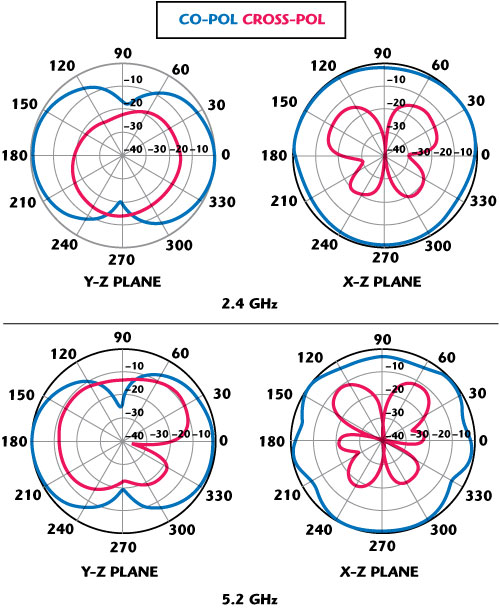
Figure 6 Measured radiation patterns in the y-z and x-z planes for the proposed antenna.
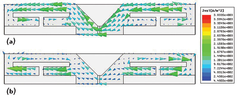
The far-field radiation patterns were measured and calibrated in a STUT anechoic chamber. Figure 6 shows the measured radiation patterns at 2.4 and 5.2 GHz in both the x-z and y-z planes. Since the feed line is located parallel to the y-axis, the y-z plane radiation pattern of the proposed antenna has nulls in +y-direction and -y-direction. It is noted that the radiation pattern in the x-z plane of the antenna is with omni-directional radiation characteristics. Figure 7 shows the measured antenna peak gain against frequency. The antenna gain is 2.77 dBi at 2.4 GHz and 4.18 dBi at 5.2 GHz. Figure 8 shows the simulated surface current at 2.4 and 5.2 GHz for the proposed antenna. It can be observed that these currents circulate in two current paths in this structure.

Figure 7 Measured antenna gain at (a) 2.4 GHz and (b) 5.2 GHz.
Conclusion
The antenna proposed in this article supports a dual-band operation at 2.23 to 2.62 GHz and 4.84 to 5.38 GHz for WLAN applications, with good radiation characteristics in both operating WLAN bands. The proposed antenna has a simple structure, low profile and small dimensions. Therefore, it will be an attractive candidate for WLAN applications and is very suitable for installation in notebook computers, PDAs and other portable devices.
References
1. M.H. Jamaluddin, M.K.A. Abd. Aziz and A. Asrokin, “Microstrip Dipole Antenna Analysis with Different Width and Length at 2.4 GHz,” 2005 Asia-Pacific Conference on Applied Electromagnetics Proceedings, pp. 41-44.
2. C.M. Su, H.T. Chen and K.L. Wong, “Printed Dual-band Dipole Antenna with U-slotted Arms for 2.4/5.2 GHz WLAN Operation,” Electronics Letters, Vol. 38, No. 22, October 2002, pp. 1308-1309.
3. H.M. Chen, J.M. Chen, P.S. Cheng and Y.F. Lin, “Feed for Dual-band Printed Dipole Antenna,” Electronics Letters, Vol. 40, No. 21, October 2004, pp. 1320-1322.
4. P. Nepa, G. Manara, S. Mugnaini, G. Tribellini, S. Cioci, G. Albasini and E. Sacchi, “Differential Planar Antennas for 2.5/5.2 GHz WLAN Applications,” 2006 IEEE Antennas and Propagation Society International Symposium Digest, pp. 973-976.
5. L.N. Zhang, S.S. Zhong, X.L. Liang and C.H. Li, “Compact Meander Monopole Antenna for Tri-band WLAN Application,” Microwave and Optical Technology Letters, Vol. 49, No. 4, April 2007, pp. 986-988.
6. Y. Ge, K.P. Esselle and T.S. Bird, “Small Quad-band WLAN Antenna,” 2005 IEEE Antennas and Propagation Society International Symposium Digest, Vol. 4B, pp. 56-59.
Wen-Shan Chen received his BS degree in electronic engineering of technology from the National Taiwan Institute of Technology (now known as the National Taiwan University of Technology) and his PhD degree from Sun Yat-Sen University, Taiwan, ROC, in 2001. From 2001 to 2002, he was an assistant professor at the Chien-Kuo Institute of Technology, Taiwan, ROC. He is currently an assistant professor in the department of electronic engineering at Southern Taiwan University, Taiwan, ROC. His research interests include antenna design RF and microwave circuits.
Shih-Hung Cheng received his BS degree from Southern Taiwan University, Taiwan, ROC, in 2007. He is currently studying for his master’s degree in the department of communication engineering at Southern Taiwan University. His main research interests include printed antennas for wireless communications, especially for WLAN applications.