
Microstrip stepped-impedance low-pass filters using fractal shapes, such as Koch islands and Sierpinski carpets, are proposed for the first time. Conventional stepped-impedance low-pass filters are very popular, due to their ease of implementation in either microstrip or coplanar technology. However, to achieve a low-pass filter with high stopband performance, techniques such as increasing the high- to low-impedance ratio will degrade the passband performance because of sharp current discontinuities in the high-low steps. By proper design, the sharp current discontinuities can be smoothed by constructing the low-impedance sections with fractal-shaped geometries, thus the passband performance of the microstrip stepped-impedance low-pass filters is enhanced greatly. To verify the proposed method, low-pass filter prototypes, constructed with different fractal-shapes of different iteration orders, are designed, fabricated and measured, and the results show that the maximum return loss level is greatly reduced, either using Koch or Sierpinski fractals, while the other performance parameters are not changed.
A compact and high performance microwave low-pass filter (LPF) is highly desirable to suppress harmonics in wireless communication systems, such as satellite and mobile communication systems. One of the conventional filters used is the stepped-impedance low-pass filter, mainly because of its ease of fabrication in either microstrip or coplanar technology. The filter is normally composed of alternating low and high impedance regions, where the change in impedance is controlled by the line width of the strip. In order to achieve a high degree of attenuation in the stopband, it is necessary to increase the order of the filter or obtain a large high to low impedance ratio (Zh / Zl).1,2 However, if the filter order is increased, the size of the entire circuit will be larger, and if the impedance ratio is large enough, the passband performance will be degraded because of the sharp current discontinuities in the high-low steps.
To enhance the passband performance for a low-pass filter with a large impedance ratio, electromagnetic bandgap (EBG) structures are used.3-6 However, since the frequency selective properties of electromagnetic bandgap structures are based on the well-known Bragg effect, their period scales with the signal wavelength, and hence the dimensions of the structure might be too high (in certain applications) to achieve the desired rejection levels. Furthermore, this kind of structure cannot be attached to a metal plane. Since microwave components are always enclosed in a metal box to shield radiation to or from other microwave components, the use of electromagnetic bandgap structures will cause enclosure difficulties. High performance microstrip stepped-impedance low-pass filters with lumped elements have been proposed;7,8 however, the use of lumped elements raises fabrication difficulties and manufacturing repeatability is difficult to maintain.
Recently, fractal-shaped coupled-line microstrip bandpass filters9 and stepped-impedance transformers10 have been proposed. Because of the weak current discontinuities of the fractal-shaped geometry in the passband, fractal-shaped bandpass filters and stepped-impedance transformers have achieved high performances. Based on these reports, fractal-shaped microstrip stepped-impedance low-pass filters were proposed for the first time by the authors,11 and some preliminary results were discussed, such as the simulation and experimental results of the Koch fractal-shaped microstrip stepped-impedance low-pass filters. However, the general characteristics of the fractal-shaped low-pass filters were not mentioned, and the reasons for the passband enhancement abilities of the fractal-shaped low-pass filters were also not discussed. In this article, an in-depth insight to the behavior of the general fractal-shaped microstrip stepped-impedance low-pass filters is provided, and the reasons for the passband enhancement abilities of the fractal-shaped low-pass filters are discussed through the simulated current distributions of the structures. The main properties of fractal geometries, such as the Koch islands and Sierpinski carpets, are reviewed and the design procedure of the fractal-shaped microstrip stepped-impedance low-pass filters is presented. The simulation and measurement results for the designed microstrip stepped-impedance low-pass filters are given. A detailed analysis of the reasons for the passband enhancement abilities of the fractal-shaped low-pass filters is also presented. Through the current distributions of the low-pass filters based on the simulation results, it will be demonstrated that, with the use of the fractal-shaped geometries, the current discontinuities in the passband caused by the high-low impedance steps are reduced greatly, and the resultant passband performance is thus enhanced, while the stopband performance remains virtually unchanged.
Fractal Geometries and Their Application on Microstrip Stepped-Impedance Low-Pass Filters
Koch and Sierpinski Fractal Geometries
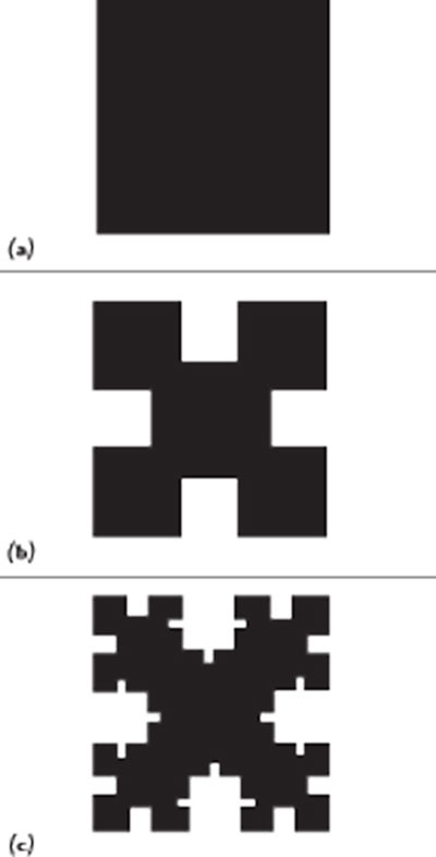
Figure 1 Koch fractal island shape whose iteration factor is 1/4 (a) iteration order 0, (b) iteration order 1, (c) iteration order 2.
Nowadays, fractal theory is widely applied to microwave engineering, such as in circuit designs,9-12 in antenna designs,13,14 and in frequency selective surface designs.15,16 The classical fractal geometries are Koch and Sierpinski fractal geometries, which are named after the Dutch mathematician Helge von Koch and Polish mathematician Sierpinski, respectively. The other fractal shapes are mainly derived from these two shapes, so the general behavior of the fractal-shaped microwave components can be derived from the behavior of the components that employ these two fractal geometries. No matter which kinds of fractal shapes are used, they are characterized by two factors: The iteration factor (fractal factor) and the iteration order. The iteration factor represents the construction law of fractal geometry generation and the iteration order depicts how many iteration processes are carried out. For a conventional square, it has numerous fractal shapes. Figure 1 shows the generation process of a Koch island whose iteration factor is 1/4, and Figure 2 shows the generation process of a Sierpinski carpet whose iteration factor is 1/3. Increasing the iteration order of the fractal geometry infinitely would produce the ideal fractal structure that shows self-similarity. The multiband and wideband properties of the fractal antennas are a consequence of its self similarity. In this article, the fractal-shaped structures are applied to the design of microstrip stepped-impedance low-pass filters, and it will be demonstrated that the sharp current discontinuities of the high-low microstrip steps can be greatly smoothed, when the low-impedance microstriplines are made with fractal shapes.
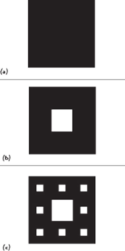
Figure 2 Koch fractal island shape whose iteration factor is 1/3 (a) iteration order 0, (b) iteration order 1, (c) iteration order 2.
Design of the Fractal-shaped Microstrip Stepped-impedance Low-pass Filters
Based on the construction law of the Koch islands and Sierpinski carpets mentioned above, the fractal-shaped stepped-impedance low-pass filters were designed in microstrip technology. The specifications are given by the cut-off frequency (fc = 2.5 GHz), filter order (sixth-order) and frequency response (maximally flat Butterworth). The design of the structure is a two-step process.

Table 1 Physical parameters of the conventional microstrip stepped-impedance low-pass filter.
First, the conventional layout of the filter is obtained according to the standard procedure. To this end, the characteristic impedances of the high and low impedance sections have been set to Zh = 120 Ω and Zl = 15 Ω, respectively. From these values, the electrical length of each transmission line section has been obtained following the standard design formulas.1 By using a commercial transmission line calculator (Agilent LineCalc), the geometry of the filter has been determined for a Rogers RT/Duroid 5880 substrate with a thickness h = 0.78 mm and a dielectric constant ε= 2.2. To provide space for the connectors, 50 Ω access lines have been cascaded at the input and output ports. The physical parameters of the designed conventional microstrip stepped-impedance low-pass filters are listed in Table 1, where i is the filter section number, Z is the impedance of the section, and w and l are the width and length of the microstrip line, respectively.
The second step consists of constructing the low-impedance sections, where the conductor strip width is substantial, as Koch islands and Sierpinski carpets of different iteration numbers, to enhance the passband of the filter. The iteration orders of the fractals are limited to two because of manufacturing tolerance. Thus, the Koch and Sierpinski fractal-shaped microstrip stepped-impedance low-pass filters with different iteration orders are determined.
Results and Analysis
Simulation Results
The designed Koch and Sierpinski fractal-shaped microstrip stepped-impedance low-pass filters with different iteration orders are simulated using the finite-element-method (FEM)-based software Ansoft HFSS 10.0; the simulated frequency responses are shown in Figure 3.

Figure 3 Simulated response of fractal-shaped stepped-impedance low-pass filters with different iteration orders; (1) Koch and (b) Sierpinski.

Table 2 Summary of results.
As can be seen, the two kinds of fractal-shaped low-pass filters show great passband performance enhancement abilities. The simulation results of these filters are summarized in Table 2, where F is the fractal shape, Iter is the iteration number, MRL is the maximum return loss in the passband in dB, CF is the cut-off frequency in GHz, SL is the selectivity17 in dB/Hz, 2H-IL is the second harmonic insertion loss in dB and 2H-F is the operating frequency corresponding to 2H-IL. The maximum return-loss level of the passband of the Koch fractal-shaped microstrip stepped-impedance low-pass filters decreased from -19.8 dB for K0, to a value below -30 dB for K2, and the maximum return-loss level of the passband of the Sierpinski fractal-shaped microstrip stepped-impedance low-pass filters is decreased from -19.8 dB for S0, to -30.35 dB for S2. It is also observed that the higher the iteration order, the lower the maximum return-loss level becomes. Nevertheless, these results reveal that the proposed technique is very promising for the design of microstrip stepped-impedance low-pass filters with improved passband. Because the sharp current discontinuities in the high-low steps are smoothed by the fractal shapes, and the performance of the stopband is decided by these current discontinuities, the stopband performance of the fractal-shaped microstrip low-pass filters all degraded a little. However, the degenerations have not changed the overall performance of the low-pass filters.
Measurement Results

Figure 4 Prototypes of the Koch and Sierpinski fractal-shaped microstrip stepped-impedance low-pass filters.
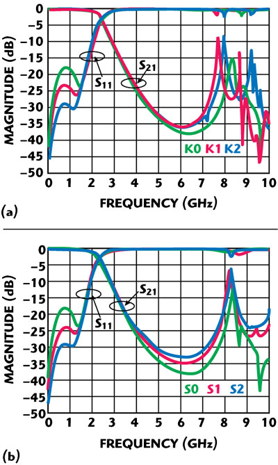
Figure 5 Measured response of fractal-shaped stepped-impedance low-pass filters with different iteration orders; (1) Koch and (b) Sierpinski.
The final fractal-shaped microstrip stepped-impedance low-pass filters were fabricated and the prototypes are shown in Figure 4. All prototypes were measured using a HP8720ET vector network analyzer, and the measured frequency responses are shown in Figure 5. As can be seen, the fractal-shaped low-impedance sections have zigzag/forklike width distributions of great complexity along the structure with the aim to suppress the sharp current discontinuities caused by high-low steps at their resonant frequency. It is not difficult to see the essence of the passband enhancement abilities of the fractal-shaped microstrip stepped-impedance low-pass filters, which is reducing the sharp current discontinuities in the high-low steps by smoothing the strip width variations. The measured frequency response agreed well with the simulated frequency response with slight discrepancies. The slight discrepancies between simulation and measurement are due to tolerances that are inherent to the fabrication process and are especially critical as a consequence of the small fractal dimensions and narrow strips for the high impedance sections. The experiment results of these filters are summarized in Table 2. The maximum return loss level of the passband of the Koch fractal-shaped low-pass filter is reduced from -17.8 to -28.6 dB, and the maximum return loss level of the passband of the Sierpinski fractal-shaped low-pass filter is reduced from -17.8 to -28.8 dB. Although the stopband performance is degraded a little, it seems that the iteration order has no relation to the performance degeneration.
Analysis

Figure 6 Current distribution of the fractal-shaped microstrip stepped-impedance low-pass filter at 0.8 GHz; (a) Koch and (b) Sierpinski.
In order to have a direct view of the current discontinuities smoothing effect of the fractal shapes on the microstrip stepped-impedance low-pass filters, the characteristics of the fractal-shaped microstrip stepped-impedance low-pass filters were analyzed, based on the simulation results using Ansoft HFSS 10. Figure 6 shows the current distributions of the designed microstrip low-pass filters employing Koch and Sierpinski fractal-shapes, when operating at 0.8 GHz. The current discontinuities of the conventional microstrip stepped-impedance low-pass filter are very strong, especially at the edges of the high-low-steps and in the middle of the low-impedance sections, resulting in high reflection loss levels. For the fractal-shaped microstrip stepped-impedance low-pass filters, such as K2 and S2, the current discontinuities are smoothed mainly due to the gradual changes in the strips at the high-low steps of the fractal-shaped microstripline, so low reflection loss levels are provided.
Conclusion
It has been demonstrated that the passband performance of a microstrip stepped-impedance low-pass filter can be improved by merely constructing the low impedance sections with fractal shapes, such as Koch and Sierpinski fractal shapes. By properly increasing the iteration order of the fractal shapes, it has been experimentally found that the maximum return-loss level of the filter can be greatly reduced, with no major effect on the stopband. The main advantages of this technique are: (1) no extra area is added; (2) the stopband is virtually unaltered; (3) no lumped elements are added; and (4) the conventional design methodology of the filter holds. To the best of our knowledge, this is the simplest approach for the passband enhancement of the microstrip stepped-impedance low-pass filter reported so far. The idea can be applied to other technologies such as coplanar-waveguide, stripline, etc.
Acknowledgments
This work has been supported by the National High Technology Development Program (863) of China under contracts 2003AA005044. The authors are also indebted to the 206th Institute of CWI Group for fabrication and measurement support.
References
1. G.L. Matthaei, L. Young and E.M.T. Jones, Microwave Filters, Impedance-matching Networks and Coupling Structures, Artech House Inc., Norwood, MA, 1980, pp. 255-353.
2. D.M. Pozar, Microwave Engineering, Second Edition, John Wiley & Sons Inc., Hoboken, NJ, 1998, pp. 474-485.
3. D. Ahn, J.S. Park, C.S. Kim, J. Kim, Y. Qian and T. Itoh, “A Design of the Low-pass Filter Using the Novel Microstrip Defected Ground Structure,” IEEE Transactions on Microwave Theory and Techniques, Vol. 49, No. 1, January 2001, pp. 86-93.
4. S. Sun and L. Zhu, “Stopband-enhanced and Size-miniaturized Low-pass Filters Using High-impedance Property of Offset Finite-ground Microstrip Line,” IEEE Transactions on Microwave Theory and Techniques, Vol. 53, No. 9, September 2005, pp. 2844-2850.
5. F.R. Yang, K.P. Ma, Y. Qian and T. Itoh, “A Uniplanar Compact Photonic Bandgap (UC-PBG) Structure and its Applications for Microwave Circuit,” IEEE Transactions on Microwave Theory and Techniques, Vol. 47, No. 8, August 1999, pp. 1509-1514.
6. S.Y. Huang and Y.H. Lee, “Tapered Dual-plane Compact Electromagnetic Bandgap Microstrip Filter Structure,” IEEE Transactions on Microwave Theory and Techniques, Vol. 53, No. 9, September 2005, pp. 2656-2664.
7. W.H. Tu and K. Chang, “Compact Microstrip Low-pass Filter with Sharp Rejection,” IEEE Microwave and Wireless Components Letters, Vol. 15, No. 6, June 2005, pp. 404-406.
8. J.W. Sheen, “A Compact Semi-lumped Low-pass Filter for Harmonics and Spurious Suppression,” IEEE Microwave and Wireless Components Letters, Vol. 10, No. 3, March 2000, pp. 92-93.
9. I.K. Kim, N. Kingsley, M. Morton, J. Papapolymerou, M.M. Tentzeris and J.G. Yook, “Fractal-shaped Microstrip Coupled-line Bandpass Filters for Suppression of Second Harmonic,” IEEE Transactions on Microwave Theory and Techniques, Vol. 53, No. 9, September 2005, pp. 2943-2948.
10. W.L. Chen, G.M. Wang, Y.N. Qi and J.G. Liang, “Fractal-shaped Stepped-impedance Transformers for Wideband Applications,” Microwave and Optical Technology Letters, Vol. 49, No. 7, July 2007, pp. 1628-1630.
11. W.L. Chen, G.M. Wang and Y.N. Qi, “Fractal-shaped Hi-lo Microstrip Low-pass Filter with High Passband Performance,” Microwave and Optical Technology Letters, Vol. 49, No. 10, October 2007, pp. 2577-2579.
12. W.L. Chen, G.M. Wang and Y.N. Qi, “A Compact Wide-stopband Koch-shaped Electromagnetic Bandgap Microstrip Low-pass Filter,” Microwave Journal, Vol. 50, No. 10, October 2007, pp. 160-166.
13. C.P. Baliarda, J. Romeu, R. Pous and A. Cardama, “On the Behavior of the Sierpinski Multiband Antenna,” IEEE Transactions on Antennas and Propagation, Vol. 46, No. 4, April 1998, pp. 517-524.
14. J.P. Gianvittorio and Y.R. Samii, “Fractal YAGI Antennas: Design, Simulation and Fabrication,” Microwave and Optical Technology Letters, Vol. 41, No. 5, March 2004, pp. 375-379.
15. J. Romeu and Y.R. Samii, “Dual-band FSS with Fractal Elements,” Electronics Letters, Vol. 35, No. 9, April 1999, pp. 702-703.
16. J. Romeu and Y.R. Samii, “Fractal FSS: A Novel Dual-band Frequency Selective Surface,” IEEE Transactions on Antennas and Propagation, Vol. 48, No. 7, July 2000, pp. 517-524.
17. N.C. Karmakar and M.N. Mollah, “Investigations into Non-uniform Photonic-bandgap Microstripline Low-pass Filters,” IEEE Transactions on Microwave Theory and Techniques, Vol. 51, No. 2, February 2003, pp. 564-572.