
This article describes a handy design method for a long backfire antenna, called for short a backfire antenna (BFA). It consists of the following basic elements: A feed F (dipole or assembly of crossed dipoles), a surface wave (SW) structure S (dipole array, metal disk-on-rod, dielectric rod, dielectric-covered metal rod or endfire dipole array), and two parallel disk reflectors: A small or feed R1 and a big or surface-wave reflector R2. The SW structure in use is a metal disk-on-rod (cigar) construction, although the same design method can be applied to backfire antennas with other types of SW rods. The presented design scheme is based on simple empirical equations, graphs and tables, and is validated by measurements of BFA prototypes with disk-on-rod structures, two to four wavelengths long, though by a simple extrapolation the scheme can be extended to antennas up to six wavelengths long. The gain range from 17 to 25 dB is covered by 2 to 5λ backfire antennas operating at the lower microwave WLAN, ISM, GPS and other bands between 1.5 and 3.5 GHz.
As a specific case, a 4λ backfire disk-on-rod antenna for the WLAN/ISM frequency band 2.4 to 2.5 GHz was designed, built and studied experimentally. To obtain a maximum gain of approximately 24 dBi, the big antenna reflector was made with a plane-conical profile. This BFA was contrasted to a commercial parabolic antenna of similar gain and dimensions, and it was found that for the chosen frequency band and required gain the well optimized BFA is a more compact and effective radiator.
The backfire antenna (BFA) was created by H.W. Ehrenspeck and his associates at the Air Force Cambridge Research Center, Bedford, MA, in 1959.1,5 Because of its compact and robust construction and very good radiation performance, this antenna has been used in various wireless systems, mostly military, earth and spacecraft. A BFA comprises an axial surface wave (SW) structure typically 2 to 4 wavelengths long. If the BFA is equal or shorter than one wavelength, the SW structure becomes unnecessary and the antenna is converted into a short backfire antenna (SBFA). The SBFA is very popular today, mainly in satellite communications and WLAN links. It has a medium directivity and gain of approximately 12 to 16 dB. For long-range point-to-point applications, say WLAN, WISP and satellite links, a bigger gain from 17 to 25 dB is desired, and the BFA along with the parabolic dish antenna (PDA) and antenna dipole arrays proved to be very good choices. For comparison, a 4 long S-band BFA, with a Yagi-type SW structure, is almost comparable in gain to an array of 16 (4 x 4) Yagi antennas, each of them comprised of nine elements.6 Both antennas, the BFA and the Yagi array, have a gain of approximately 23.5 dB, but while the BFA has sidelobe levels more than 20 dB below the main lobe, the Yagi array sidelobes are much higher (-11 dB). Furthermore, the BFA is more compact, has a simpler feed system and reduced complexity.

Figure 1 Simplified operation of the back-fire antenna: (a) geometry, (b) end-fire antenna model and (c )image model.
The BFA geometry is illustrated in Figure 1. It consists of the following basic elements: A feed F (dipole or assembly of crossed dipoles), SW rod S (dipole array, metal disk-on-rod, dielectric rod, dielectric-covered metal rod or endfire dipole array), and two parallel disk reflectors: A small or feed reflector R1 and a big or surface-wave reflector R2. In the figure, the antenna length L is the distance between R1 and R2.
The dipole feed location between the two reflectors is of great importance for the BFA radiation and input characteristics. The antenna works normally only for two feed locations: Superior, if the feed F is near the small reflector R1, and inferior, if F is near the big reflector R2. In both cases, the distance between the feed and respective reflector is λ/4. Other feed location points along the SW structure are not recommended. In this article, only a BFA with superior feed location has been considered, since it has approximately 3 to 4 dB higher gain, compared to the BFA with inferior feed location.6,7
The simplified radiation mechanism of a BFA has been described in early references1-5 and can be summarized as follows. A larger amount of the spherical wave radiated from F is transformed by S into a traveling wave, aimed at the big reflector R2. The feed or launching efficiency is measured as the ratio between the power carried by the surface wave and the total radiated power. Thus, the feed efficiency is considered big if the power coupled to the spherical wave is small compared to power tied to the surface wave. If R2 is not present, the assembly R1-F-S acts as an endfire antenna (EFA) with an effective aperture of diameter De1 radiating in the axial direction. The big reflector R2 turns back the surface wave towards the BFA virtual aperture, where it is partially reflected by the small reflector R1. Thus, according to this simple image approach, R2 forces the surface wave to traverse the physical antenna length L at least twice. As a result, the BFA operates as an EFA of effective length equal to double the physical length, or Le = 2 L. Consistent with the Hansen-Woodyard (HW) condition,5,8 the maximum gain of the EFA is proportional to the length of its surface wave structure, provided that the SW phase velocity v is adjusted to its optimum value corresponding to the effective length Le. This implies that the BFA design may have an effective radiation aperture of diameter De much larger than the corresponding endfire aperture De1. The BFA with an optimum SW phase velocity v (Le = 2 L) should yield as a minimum four times (6 dB) higher gain than the EFA having an optimum SW phase velocity v (L).
More rigorous theoretical and further experimental studies of the BFA6,8 have revealed that the successive SW reflections (and diffractions) by the small and big reflectors produce more complicated standing-wave field modes between them. The best BFA gain performance is obtained if the antenna physical length is approximately equal to a multiple of the free-space half wavelength. Our experiments with backfire antennas have shown that Le equal to 6L is a better choice in finding the optimum surface wave velocity. Such approximation of the inner standing wave process corresponds to six forward and backward travels along the surface wave structure or to a triple wave reflection from the big reflector.
Relations Between Surface-wave Phase Velocity and Antenna Length
Based on the experimental and computer phase visualization of the EFA, it is assumed2,6,8 that at its end plane, in the limits of so-called critical angle Ψc (or if Ψ ≤ Ψc), the SW has a quasi-plane phase front and effective radiation aperture of diameter De1. Otherwise, if Ψ > Ψcr, the phase surface wave front looks like a spherical one. This deviation from the plane SW is due to the primary feed field radiated directly as a free-space spherical wave. The critical angle depends on the SW phase velocity v and is approximately found by2,4
where

Here, v (L/λ) is the SW velocity delay factor as a function of the length expressed in wavelengths. Equation 2 is derived from the simplified single-image model of BFA and the Hansen-Woodyard optimum phase condition for a surface wave rod with an effective length Le = 2 L; c is the free-space wave velocity.2,5 The ideal image model is introduced2 for the case of a big reflector of infinite dimension. The multiple reflection and diffraction effects on both reflectors and the feed dipole should also be taken into account. The studies have shown6-8 that the simple image model and Equation 2 are not suitable for making a correct BFA design, and thus, a bigger Le should be chosen.
Here, an effective BFA length that is equal to six physical lengths is supposed, that is Le = 6 L. This assumption corresponds to six wave travels along the physical antenna length or three reflections from the big reflector. For Le = 6 L, Equation 2 is modified to

Figure 2 Phase velocity factor vs. length for different number of reflections from the big reflector.
Figure 2 illustrates the change of velocity delay factor ξS as a function of the BFA antenna physical length L in wavelengths, calculated for an effective length Le equal to 2L (blue line or Equation 2) and 6L (red line or Equation 3). Three measured values3,7 of the SW velocity delay factor versus the physical antenna length expressed in wavelengths, or=ΨS (L/λ), for an optimally designed disk-on-rod BFA SW rod: ΨS =1.05, 1.03 and 1.02 for L/λ = 2, 3 and 4, are shown with circles. These points agree well with Equation 3 and the corresponding red line.
As mentioned in the previous section, the BFA can be considered as a parallel-plane resonator antenna with a standing surface wave field excited inside. In the antenna aperture that is partially closed by the small reflector R1 two basic wave phenomena take place: Multiple partial reflections from R1 and multiple intensive radiations from the open aperture area. The length of such radiating cavity can be expressed as

where λS = v/f is the surface-wave wavelength, ΔL is the length correction due to the radiation, n is a real integer called standing-wave number and f is the design (resonance) frequency.
On the other hand, the BFA studies have shown that its length L takes discrete resonance values, equal to n free-space half wavelengths, or

where n has the same integral values as in Equation 4.
In practice, the standing-wave number n usually takes values from 4 to 8 to which correspond the next five values of L/λ = 2, 2.5, 3, 3.5 and 4. For n = 1, the BFA is just a half-wavelength long and becomes a short backfire antenna or SBFA. In this case, the SW structure is missing.
The length correction ΔL in Equation 4 is found by the equality of Equations 4 and 5, or

From Equations 3 and 5, the backfire antenna Equation 6 becomes
ΔL is small compared to the BFA length L. For instance, if L/λ varies from 2 to 4, the ratio ΔL ranges from 0.038 to 0.02.
Big Reflector Profiles

Figure 3 Big reflector profiles.
Four different profiles of the big reflector are shown in Figure 3: (a) disk reflector R2 of diameter D2, (b) rimmed disk reflector R2RM of diameter D2R, (c) rimmed stepped-corrected disk reflector R2S of diameter D2S and (d) rimmed conically-corrected disk reflector R2C of diameter D2S.7 The effective diameter De1 of the EFA effective aperture area depends on the antenna length L and the critical angle Ψcr, or

which, having in mind Equation 4, can be approximately given as a function of L/λ as
In the image model, the big reflector of BFA lays in the EFA effective aperture plane and its minimum diameter D2 is equal to the constant-phase effective aperture, or D2 = De1.
With the increase of the disk diameter, so that Ψ > Ψcr, the phase front becomes spherical and a quadratic phase distortion on the reflector plane occurs. If the tolerable phase distortion at the disk edge is π/2, the disk diameter D2 set equal to De will be bigger than De1, and can be found roughly as2

The disk reflector R2R with a quarter-wavelength rim (w1 = 0.25λ) has a diameter D2R equal to that of reflector R2, that is D2R = D2. The rim reduces the sidelobe and backlobe levels, and results in an antenna gain increase.
The step-phase correction in reflector R2S and the conical-phase correction in reflector R2C allow further enlargement of reflector diameter and antenna gain. These two reflectors are normally used for antenna lengths equal or greater than 3λ. The inner or disk area diameter D20, and the outer (peripheral) diameters D2S and D2C of the two reflectors R2S and R2C, respectively, are given by2,6

The step width w2 and rim width w1 are also chosen equal for both reflectors, or

Though the BFA with large reflectors R2S and R2C are equal in diameter, the phase-correction in the latter is slightly better and the antenna gain is a bit higher.2 Naturally, the compound plane-parabolic reflector will have the best phase correction, but this would require more complex fabrication technology.
Note: The equations and experimental results for the antenna parameters presented next are applicable for backfire antennas having either type of big reflectors: R2R or R2C. The study concentrated on them only, because the BFA antenna with reflector R2R is of simpler construction and has fairly low side and back lobes, while the BFA antenna with reflector R2C produces higher gain, compared to the other antenna's reflectors.
Small Reflectors
The small reflector R1 in all BFA antennas is usually a simple thin disk with a diameter D1. It has a great importance on the SW launch process and aperture field distribution. For very small values of D1, the BFA essentially radiates as an EFA. For a constant big reflector diameter and antenna length, the small reflector has an optimum diameter for which the BFA antenna reaches a maximum gain. If D1 is bigger than its optimum size, the antenna gain reduces, and for values of D1 close to the big reflector diameter, the antenna practically does not radiate as it is transformed into a very high quality-factor resonator. The experimental study has proved that, for all types of big reflector, the BFA small reflector optimum diameter can be found by7

With the BFA length increasing, both the big and the small reflectors grow in diameter according to the quadratic relations in Equations 10 to 12 and 14. The minimum and maximum values in Equations 11, 12 and 14 define the optimum ranges of diameters D20, D2S (or D2C) and D1 in different practical BFA designs. They have been validated for BFA lengths from 2λ to 4λ.1-4,6,7
Directive Gain and Beam width
In what follows, the empirically obtained equations for the directive gain G of EFA and BFA as a function of L/λ (the directive gain or directivity will be simply called the gain) are listed.
Gain of EFA
This antenna should be designed according to the original HW phase condition, where Le = L and the SW velocity v(L/λ) satisfies the equation S(L/) = 1 + 0.46 λ/L. Under this condition, the gain of a very long homogeneous EFA is proportional to L/λ, or5,8

If the design is based on the HW phase condition and the SW rod is tapered accordingly, the gain of the EFA for L between 3 and 8λ is5,8

Gain of BFA
The BFA gain is much higher than the gain of EFA and can be found by the basic aperture antenna equation8,9
where Ae = π(De/2)2 is the effective aperture area, expressed by the effective aperture diameter De. In decibel form, Equation 17 is given by

In Equation 18, De = D2R for the rimmed disk reflector is calculated with Equation 10, and for a rimmed disk-conical reflector De = D2C, by Equation 11; ηe is the radiation efficiency, which takes into account the field amplitude distribution in the BFA effective aperture.
Independently of the partial blockage by R1, the BFA has a relatively constant field distribution outside the blocked aperture area, which makes the aperture radiation efficiency too big. In accordance with the gain measurements, ηe may be set as ηe = 0.6 to 0.8.
The average antenna beamwidth may be defined as,

in degrees, where BE and BH are the E- and H-plane -3 dB beamwidths. If the BFA has a phase-corrected big reflector R2C its average beamwidth can be found approximately by6

Knowing B, the BFA gain can be computed by the following empiric equation, valid for a moderately high gain aperture antenna8,9

Equation 19 is not valid for the BFA with a rimmed disk reflector R2R, which for the same SW rod length has a much smaller effective aperture. Equation 19 was corrected as follows to match better the realistic beamwidth and gain values in the case of a BFA having a reflector R2R

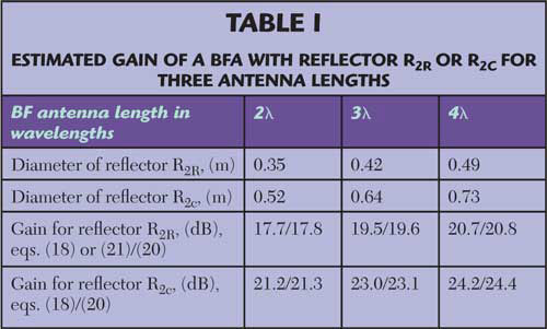
Table 1 illustrates the gain property of BFA depending of the large reflector size and shape, and SW rod length. The gain values have been estimated by use of Equations 18 or 20 in the case of reflector R2C or by Equations 18 or 21 and 20 for a BFA with reflector R2R. From this table, it is evident that for all BFA lengths, the use of the plane-conical reflector R2C leads to an approximately 3.5 dB higher gain, compared to a BFA with a plane reflector R2R. On the other hand, if a gain of approximately 20 to 21 dB or less is needed, the more compact and simpler BFA having a reflector R2R is to be preferred. For instance, the 2-long BFA with reflector R2C has approximately the same gain as the 4-long BFA with a reflector R2R, but the former is of more complex construction and occupies 1.5 times as much volume. The studies have shown that the more complex BFA with a phase-correcting reflector R2C (or R2S) should be considered only when gain values equal or greater than 22 to 24 dB are required.
Disk-on-rod (Cigar) Surface-wave Structure
Feed Location and Design
The phase velocity delay factor ξS (L/λ) of the SW rod is found from Equation 3 or Figure 2 (red line). For a given ξS (L/λ), the basic dimensions of the disk-on-rod (or in fact disk-on-tube) structure (see Figure 4) are: DS or the outer diameter of the SW structure rings, DT or the inner rings' diameter (outer tube diameter), and P, the disk array period (inter-disk distance). They can be found by use of the known disk-on-metal rod design procedure.9-12

Figure 4 Sketch of the surface-wave disc-on-rod structure.
The metal disk-on-rod SW structure, known also as disk-on-rod SW waveguide, usually consists of rings welded on a tube T, which serves also as an outer (shield) conductor of the feed rigid coaxial line. In a heavy-duty BFA, the disk-on-tube assembly can be replaced by a single-piece corrugated rod (tube).

Next, the design procedure of disk-on-rod surface wave structure is summarized. For a given antenna length L and design wavelength λ, the phase delay factor ξS was calculated from Equation 3. In Table 2 are some typical BFA values of ξS corresponding to different pairs of disk-on-rod dimensions ΔD = DS - DT and P. The table was prepared on the basis of two classical references on the subject.10,11 The thickness t of the disks (rings) is usually taken according to 0.01λ ≤ τ ≤ 0.02λ.
One of the possible ways of BFA feeding is by means of a dipole backed by a small reflector. All the results presented in this article have been obtained with BFA prototypes having the following feed configuration. An input coaxial-type connector is bonded at one side of a rigid feed coaxial line and fixed to the big reflector rear. The inner cylindrical conductor of the coaxial line is set along the antenna axis and is air-spaced from the outer tube conductor. On the opposite side, the feed coaxial line is short-circuited at the small reflector plane and the dipole feed F is connected to the coaxial line by means of a half-wave slot balun, known as a split coaxial line-dipole balun. This feed construction is a classical topic and can be found in many references.8,9
Practical BFA Design and Study

Figure 5 Sketch of the BGA prototype constructed.

Figure 6 Photograph of the BFA prototype.
Based on the equations listed in this article, several backfire antennas with metal disk-on-tube SW structures of different resonant lengths (L = 2λ,3 λ and 4λ), tuned at the design frequency f = 2.5 GHz and working over the frequency band of 2.4 to 2.5 GHz, were built and examined experimentally. As an example, the BFA prototype that produced the largest gain is described. This is a 4λ-long backfire antenna with a big plane-conical reflector R2C. The sketch of this antenna is shown in Figure 5 and a picture of the prototype is shown in Figure 6.

Figure 7 Measured VSWR as a function of frequency.
Figure 7 illustrates the input match bandwidth of the experimental BFA antenna. Its dimensions, design and measured parameters are listed in Table 3. The equations used for obtaining the BFA table data are quoted in round brackets.

At the design frequency of 2.45 GHz, the VSWR curve has a bare minimum of about 1.1. The input frequency bandwidth is 11 or 8.5 percent at a VSWR level of 2.0 or 1.5, respectively. This band is more than double the whole WiFi/ISM spectrum that ranges from 2.4 to 2.5 GHz. For comparison, the basic antenna data of a commercial WLAN parabolic dish antenna (PDA), operating in the same frequency band and having similar gain and radiation patterns,13 is also listed. Compared to the BFA, the PDA is not as compact and has a 35 percent less radiation efficiency. Obviously, the PDA is not acting in a typical quasi-optical manner, because its dimensions are relatively small compared to the design wavelength.
Acknowledgment
H.D. Hristov and R. Feick wish to acknowledge the financial support under the Chilean Conicyt Bicentenario Project ATC-11/2004.
References
1. H.W. Ehrenspeck, "The Backfire Antenna, a New Type of Directional Line Source," Proceedings of the IRE, Vol. 48, No. 1, January 1960, pp. 109-110.
2. F.J. Zucker, "The Backfire Antenna: A Qualitative Approach to its Design," Proceedings of the IEEE, Vol. 53, No. 7, July 1965, pp. 746-747.
3. J.A. Strom, "A Dielectric-rod Backfire Antenna," AFCRL Report 69-0347, 1969.
4. F.J. Zucker and J.A. Strom, "Experimental Resolution of Surface-wave Antenna Radiation into Feed and Terminal Patterns," IEEE Transactions on Antennas and Propagation, Vol. 18, No. 3, July 1970, pp. 420-422.
5. H. Bach, "Applicability of Hansen-Woodyard Condition," Proceedings of the IEEE, Vol. 119, No. 1, January 1972, pp. 38-40.
6. G.S. Kirov, "Engineering Method for Design of Backfire Antennas," 3rd Conference on Electronic Circuits Digest, Prague, September 1979.
7. A. Kumar and H.D. Hristov, Microwave Cavity Antennas, Artech House Inc., Norwood, MA, 1989.
8. H. Jasik, Antenna Engineering Handbook, R.C. Johnson (Editor, 3rd Edition), McGraw-Hill, New York, NY, 1999.
9. T.A. Milligan, Modern Antenna Design, John Wiley & Sons Inc., Hoboken, NJ, 2005.
10. J. C. Simon and G. Weill, "Un Nouveau Type d'Aérien - Rayonnement Longitudinal," Annales de Radioélectricité, Tome VIII, No. 33, 1953.
11. L. Thourel, Les Antennes, Dunod, Paris, France, 1971.
12. S.A. Brunstein and R.F. Thomas, "Characteristics of a Disk-on-rod Antenna," JPL Quarterly Technical Review, Vol. 1, No. 2, July 1971, pp. 87-95.
13. Cushcraft-Laird Technologies, "Wireless LAN Antennas, Parabolic Reflector Antenna S24024PDNF 2400/2500 MHz," www.cushcraft.com.
Georgi S. Kirov received his MSc and PhD degrees in radio engineering from the University of Varna, Bulgaria. In 1969, he joined the department of radio engineering and, in 1999, became the head of the department. From 1981 to 1986, he was with the University of Setif, Algeria, as a lecturer in the field of telecommunications. He specialized in microwave antennas at Moscow Technical University and the Moscow Technical University of Communications and Informatics. He was also a researcher at the University of Magdeburg, Germany. His research interests include high frequency electromagnetism, antennas and wave propagation, microwave/optical devices and wireless communications.
Hristo D. Hristov received his PhD and DSc degrees in radio engineering from the Technical University, Sofia, Bulgaria. Since 1965, he has been with the Technical University of Varna, Bulgaria. He is currently a research professor with Universidad Técnica Federico Santa Maria, Valparaiso, Chile. He was a researcher at the Strathclyde University of Technology, Queen Mary College and the Eindhoven University of Technology. His research interests include high frequency electromagnetism, antennas, propagation, microwave devices and wireless communications.
Rodolfo Feick received his degree in ingeniero civil electronico from Universidad TŽcnica Federico Santa Maria, Chile, in 1970, and his MSc and PhD degrees in electrical engineering from the University of Pittsburgh in 1972 and 1975, respectively. He has been with the department of electronics engineering at Universidad Técnica Federico Santa Maria since 1975, where he is now the head of the telecommunication group. His research interests include wireless systems and data communications.