
Simulation software is becoming more widespread in a number of industries, and the field of microwave design is no exception. The ability to create virtual prototypes has enabled designers to not only reduce the lead time on new designs, but also to try out new concepts that would otherwise prove prohibitive. With its ability to predict the performance of devices ranging from filters to antennas, Vector Fields’ CONCERTO software is a leading tool for the design of microwave devices, making it an essential part of many designers’ ‘tool kits.’
That tool kit has now been improved with Version 5 of the CONCERTO software suite having been enhanced to include a new analysis module — CLASP. The new module is based on the method of moments (MoM) technique, which is well suited for applications that include large volumes of free space. Examples include antenna placement, antenna interaction and radar cross-section (RCS) calculations. New additions to the QUICKWAVE analysis (based on the finite difference time domain (FDTD) method, incorporating Conforming Mesh technology) make it easy to use and to visualize the results. The CONCERTO Modeler has also been extended to be able to drive both analysis types.
Method of Moments Analysis
The method of moments is a well established technique for modeling problems that involve large volumes of free space. It is only necessary to include the conductor or dielectric surfaces of a model; the interior volume and exterior space are handled automatically. The surfaces are discretized using triangular elements, and thin wires are modeled using line elements. As with other integral methods, this technique leads to a matrix representation of the model to be studied, where the matrix is fully populated. Figure 1, for example, is of a generi helicopter model, showing the surface mesh required to compute the RCS or the effect of placing an antenna on the fuselage. A portion of the monostatic RCS field is also shown.

Fig. 1 A generic helicopter model (a) and a portion of the monostatic RCS filed (b).
A major advantage of the MoM is that when the matrix system has been solved once, the matrix inverse can be stored for later use. In this case the matrix inverse is passed to the Post-Processor, allowing alternate source fields to be applied with little extra computing effort. If a plane wave is required from a different angle, it is only necessary to perform a matrix back-substitution to get the new solution. This feature ensures that monostatic RCS calculations are fast and efficient (unlike the finite element or FDTD approach, for instance, which require each new plane wave direction to be re-computed afresh).
Since the air volume is not meshed when using the MoM approach, analyses such as coupling between antennas can easily be solved, as illustrated in Figure 2. Such examples include antenna placements on masts or on satellite systems.

Fig. 2 A complex antenna system (a) showing the radiated field over a spherical patch (b) and over a planar patch directly in front of the antenna (c). | 
Fig. 3 Field vectors displayed within a circular waveguide with a lossy load with a circular polarization applied (images are taken ?/4 apart). | 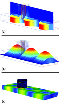
Fig. 4 Field magnitute |E| on two planes (a)(b) through a waveguide junction, and surface currents displayed on the geometry (c). |
FDTD Analysis Updated
The main analysis module in CONCERTO remains the FDTD approach, which is ideally suited to complex microwave component design. Applications can include planar as well as fully three-dimensional structures. Some major enhancements have been made to the FDTD module, both in the analysis and the result visualization.
Material modeling is one area that has received a lot of attention, and the ability to include dispersive media has been added to the software. Three models for dispersion have been used: Lorentz, Debye and Drude models, each representing a different way in which the material properties vary with frequency. Magnetized ferrites have also been included, allowing for the effects of a DC biasing magnetic field to be superimposed on a material.
The visualization of the simulation has been extended to include easier viewing of port modes and fields during the analysis. The approach used is that during the simulation process, all the field and S-parameter values can be displayed at will. Multiple windows can be opened, each showing a different aspect of the analysis as it progresses (see Figure 3). This is a completely interactive approach, and helps with the understanding of how a device actually works.
In addition to field vectors throughout the model, the fields on different planes can be displayed, as well as the surface currents on the geometry (see Figure 4). Additional features that have been added to the FDTD module include the ability to couple to 3D thermal modeling software (a basic heating module is already available, but assumes adiabatic heating — the new development allows for temperature diffusion to be modeled in addition) and to include the effect of rotating loads for microwave heating applications.
Common Modeler for Data Creation
An important part of the whole design suite is the Geometric Modeler. This has also been extended in a number of ways to meet the requirements of being able to launch both FDTD and MoM analysis modules. In particular, the mesh creation stage is different for both modules and generates quite different kinds of mesh, as illustrated in Figures 5 and 6.

Fig. 5 Finite difference grid for a TEM horn antenna.
The material definition stage is enhanced for the time domain analysis using FDTD, since dispersive materials can be added by completing a dialog with the relevant details. Figure 7 shows how this appears. All other aspects of the Modeler are common for either analysis.

Fig. 6 Closer detail of the surface triangulation used in the MoM analysis.
Probably the most useful aspect of the Modeler is its ability to store a history of the sequence of actions required to build a model, or the changes made to an imported data file created using an external CAD system. This history can be modified using a context sensitive editor built into the Modeler and saved for later use. The model can be parameterized so that key dimensions are stored as variables and the user prompted for a new value each time the model is opened. The dialogs used within the program are also open to the user so that custom dialogs can be created to make parameter definition even easier.
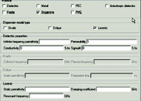
Fig. 7 A section of the material definition dialog for the FDTD solver showing the different dispersive media models and required data.
The Right Tool for the Job
The most important feature that now exists in Version 5 is the ability to choose the right tool for the job. There is no single method that can be used for all applications, and it is the Vector Fields’ approach to provide a range of tools, enabling the correct one to be selected as required. The FDTD method is the preferred choice for most microwave design needs, but is not ideal for some applications. The MoM technique is far more suitable when there are large expanses of free space that need to be modeled, and can therefore be considered complementary to the FDTD approach.
The finite element method (FEM) also has its strengths, and the SOPRANO analysis module uses this technique very successfully for RF cavity modeling, for example. The limitation encountered when using finite elements is that it is difficult to add sufficient elements to ensure the highest accuracy as the frequency increases — far less of an issue when using the FDTD approach.
Conclusion
There are three main approaches to microwave modeling, and each has strengths and areas where it can best be applied. The finite element method is already in use in the SOPRANO module, and with CONCERTO Version 5, both the FDTD and the Method of Moments are present, all launched from a common user interface. It is now possible to select from the three main solution techniques in a single environment, offering the most appropriate method tailored for the application.
Vector Fields Inc.,
Aurora, IL
(630) 851-1734,
www.vectorfields.com